2: Installation
2-2 PRC-BC4-MS
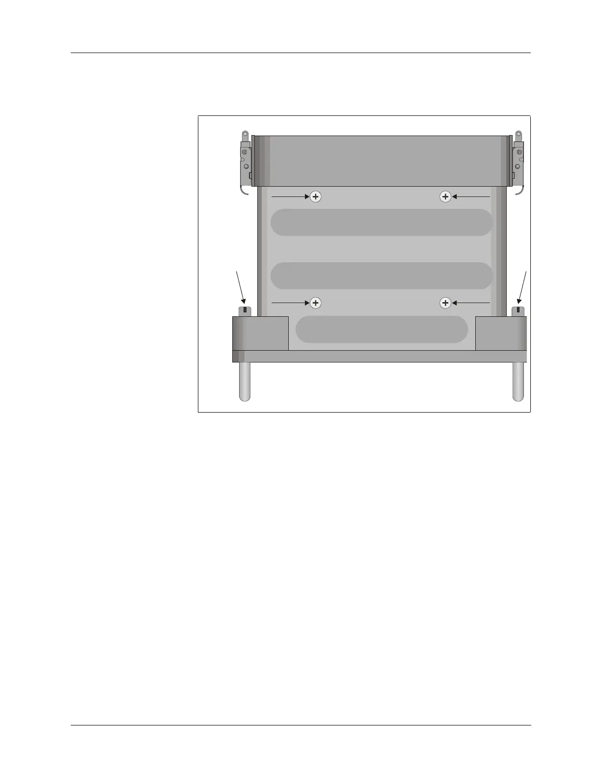
2. Place the PRC-BC4 so the front panel is faced away from you. Locate
and remove the four captive screws that hold the front panel to the case
(refer to Figure 2-1 below).
3. Place the PRC-BC4 so the bottom side is facing you. Remove the four
screws that hold the inside chassis to the case.
4. Slide the chassis out of the case.
5. Note the connections on the power transformer behind the regulator
circuit board.
To configure the PRC-BC4 for a 220 VAC power source:
1. Desolder terminals 3, 4, 5 and 6
2. Remove the jumper wires between terminal 3 and terminal 4, and the
jumper between terminal 5 and terminal 6 (refer to Figure 2-2 on page
2-3).
3. Install one of the jumpers between terminal 4 and terminal 5.
4. Resolder terminals 3, 4, 5, 6.
5. Reverse steps 2 through 4 in the previous procedure to reassemble the
PRC-BC4.
Figure 2-1 Captive and Chassis Screws
BOTTOM
VIEW
FRONT PANEL
CASE