6
• Page 5 •
Once the salt level in the pool is correct the unit may be switched on. Set Sanitiser Output to Max (100%).
The STAND - BY indicator will be On and no Cell Output will be seen for approx 30 seconds, this allows
the pool pump and lter to prime and the Cell Housing to ll with water. After this start - up delay, the display
should show 100 (ESR Models (+/-2), unless in Winter Mode where it will display 85 (ESR Models (+/-2). At
this point both Operation LED’s should be Green; if not there may be a problem. (Refer table).
DISPLAY / INDICATOR LED 1 LED 2 REASON / ACTION
STAND – BY ON Green Green
1. Start-up delay functioning.
2. Sanitiser Output set below max.
Cell is turned off. (Refer Sanitiser Output page 7)
FLOW
STAND – BY ON
Green Green
1. Gas detected. Check pump/pipes for damage.
2. Gas sensor not connected to cell.
FLUCTUATING
AROUND 100
Green Green System operating normally.
Green Red
1. Salt level too low. Add salt at a rate of 25kg per 25,000L.
2. Cell is calcied. Clean cell.
3. Water temperature low. Switch to Winter Mode.
Red Red
1. Salt level below minimum. Add Salt.
2. Cell is calcied. Clean cell.
3. Water temperature very cold. Switch to Winter Mode.
Continued operation may cause damage to system-
Consult dealer for problem rectication.
PLEASE NOTE: When Winter Mode switch is On Unit will operate similar to above except Display will
uctuate around 85. (Refer Winter Mode page 8).
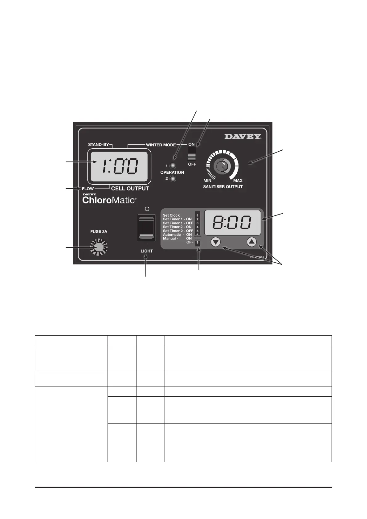
CONTROL PANEL LAYOUT
OPTIONAL POOL LIGHT
SWITCH
SELECTOR SWITCH
TIME CLOCK
SANITISER
OUTPUT DIAL
WINTER MODE SWITCH
OPERATION LED’S
UP AND DOWN
BUTTONS FOR
INCREMENTAL
SETTINGS.
SANITIZER
OUTPUT
INDICATOR
LED FLOW
INDICATOR
FUSE & FUSE
HOLDER
• STABILISER - It is essential that pool stabiliser be added and maintained at the rate of 30 - 50 ppm at all
times. Do not exceed 100 ppm.
(Refer Day to Day Operation page 12 for further information).
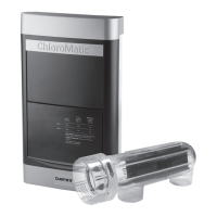
OPERATION OF YOUR ChloroMatic SYSTEM:
Cell Output on the digital LED display is expressed as a percentage. The Display will uctuate around 100
when producing chlorine - unless in Winter Mode, in which case the Display will uctuate around 85. (Refer
Winter Mode on page 8). The Unit is tted with an electronic control and warning system. This regulates the
output of the Unit to the preset maximum. The warning system consists of two Operation LED’s that will glow
Green, or Red to indicate possible faults with the Unit or damaging operating conditions.