10
Figure 5. Cartridge Removal
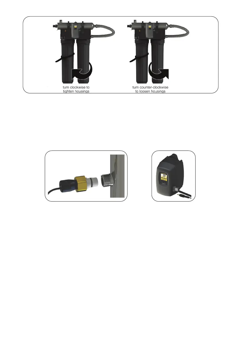
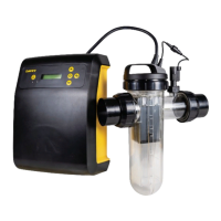
Step 9: Install the UV sensor (optional).Aligntheatportionsoitfacesthegland
nut end and matches up with the half metal lip on the sensor port (see
Figure 6). Insert the sensor so it is fully seated and hand tighten the sensor
nut. Insert the sensor connector into the IEP port located on the right side of
the controller (Figure 7). For the sensor to be recognized by the controller,
the controller power must be plugged in last. Do not plug the controller
power cord in before the last step.
Figure 6. UV Sensor Installation Figure 7. IEP Connection
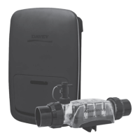
Step 10:Removethelterheadscrewsfromthetopmountingplate(4screwsfora
singleltermodeland8screwsforadoubleltermodel).
Step 11:Carefullylowerthelterhead(orheads)fromtherackassemblyandrotate
180 de-grees. Reassemble onto the rack assembly and take note of the
arrowslocatedonthetopofthelterheadsindicatingwaterow(which
nowshouldbeindicatingaowdirectionofright-to-left).Step 4:
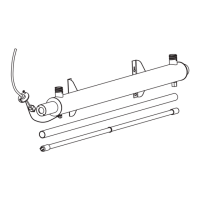
Remove the stainless steel UV reactor from the two plastic clamps located on
the top of the rack. Carefully remove the top straps securing the reactor with
the aid of a standard (slot) screwdriver). Rotate the reactor 180 degrees (with
the inlet now facing to the left and the lamp connections located towards the
right)andplacebackintothecellclampsandreafxthetwotopstraps.
Ineithertheleftorrightcongurations,tofacilitatelampremoval,ensure
there is enough space at the lamp connector end to safely remove the UV
lamp and/or quartz sleeve (See Figure 3).