EasyManua.ls Logo

Davey RainBank mkII

Davey RainBank mkII
18 pages
To Next Page IconTo Next Page
To Previous Page IconTo Previous Page
Loading...
MAINS
WATER
SUPPLY
RAINWATER
SUPPLY
TO TOILETS
AND LAUNDRY
Po
wer to pump via
3 pin socket
5 volt connection
for float switch
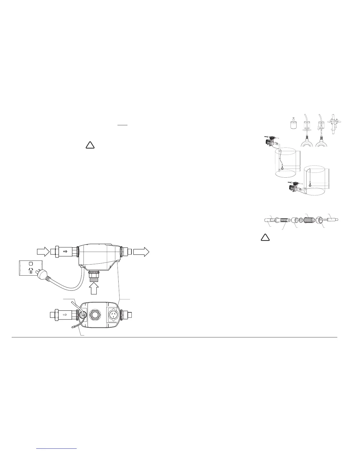
Incoming power to RainBank®
via 3 pin plug
 17
 
isolation valve be fitted to where the

®
and
between the pump and the rainwater

of the unit if required without turning
off the household water or losing
stored rainwater.
 
hemp or pipe glue. Do not use
crimped fittings.
 
rotating unions that require bracing.
 

®
unit is difficult you may
have to connect the 5 volt connection

plumbing is connected.

STEP 7
 pump power lead to


®
.
IMPORTANT

®

pump is connected to the power point
the pump will run constantly,
shortening the life of the pump and
potentially running the pump dry.
 

®
to your power point.



not necessary if you are using a

is already part of the pump.
For greater distances between your




leads can be added between the pump



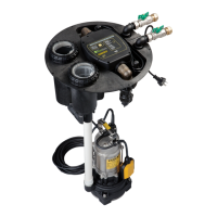
STEP 3a - TOP ENTRY FLOAT SWITCH
NOTE: THE VERTICAL POSITION OF
THE FLOAT SWITCH IN RELATION TO
THE PUMP WATER INLET IS CRITCAL
1. Measure the distance from the top of


 


3. Drill a hole in the top of the tank large
enough to suit a cable grommet or

 

 

 
firmly snap into position.
 

8. Fasten with cable grommet to

STEP 3b - ALTERNATE SIDE ENTRY
FLOAT SWITCH 32398
IMPORTANT
 
installation in polyethylene and

steel tanks but cutting through the



manufacturer before drilling.
 
installed from the outside of the tank.

 
switch is designed to work in a
100
100
100
100
C
D
E
F
A
D
E
B
A
D
E
B
100
100
100
100
C
D
E
F
A
D
E
B
A
D
E
B
100
100
100
100
C
D
E
F
A
D
E
B
A
D
E
B
Top
Bottom
Sealing grommet
Level switch stem
Bayonnet join
Sealing nut
Compression nut

Related product manuals