Operating controls
6
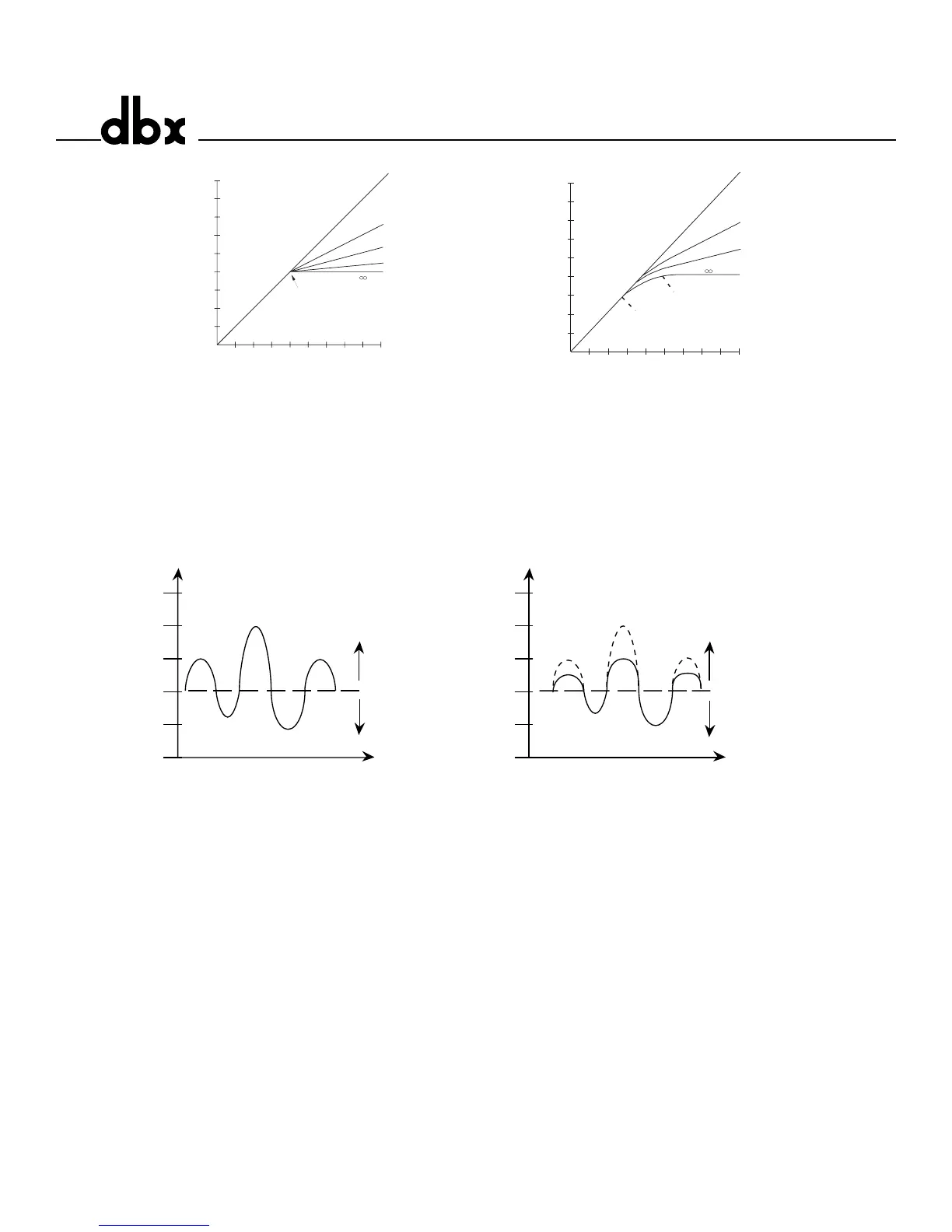
Figure 2: Hard Knee Compression Curve,and OverEasy® Compression Curve, and Threshold
LEDs.
Figure 3 shows the effect of 2:1 compression on a signal as it rises above and falls below the threshold.
Below the threshold the signal is not affected. Above the threshold, the output signal increases by only
half of the increase (in dB) of the input signal level. In other words, with a 2 dB increase in input level,
the output increases by only 1 dB, hence the 2:1 compression ratio.
Figure 3: Compression Effect on Signal Level with a 2:1 Ratio at a -20 dBu Threshold
Contour Switch - This switch adds a gentle low frequency de-emphasis into the detector path. This is
extremely useful in keeping low frequency program material from “muffling” or “punching holes in” the
compressed signal. This feature allows faster attack times and higher compression ratios with less arti-
facts. The switch will light indicating contouring is activated.
Compressor Ratio Control - This control selects the ratio between input and the output levels for sig-
nals above the level set by the COMPRESSION THRESHOLD control. It is adjustable between 1:1 and
infinity:1. Note, when OverEasy® processing is selected, the ratio transitions smoothly from the linear to
the compressed region. As the signal exceeds the threshold, the ratio approaches the ratio set by the
COMPRESSOR RATIO control.
Gain Reduction Meter - This 12 stage meter shows the amount of gain reduction due to compression,
expansion/gating, or Intelligent Predictive Limiting™, displaying gain reduction from 0 to 30 dB.
Attack Control - The ATTACK control sets the amount of time it takes the 1066 to begin compressing a
signal once the detector has sensed a signal above threshold. The ATTACK range is from 3 dB/msec
(for a tighter and more noticeable compression effect with very little overshoot) to .04 dB/msec (for more
delayed, gradual compression). A very fast ATTACK setting will cause the 1066 to act like a peak limiter