CONTENTS
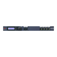
Front
panel (operation)
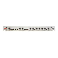
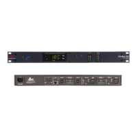
Rear panel
(connections)
Typical hookups (plug
and cable wiring)
Application
notes (gating, compression,
limiting, sidechaln).
. .
.
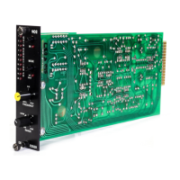
Block
diagram
Schematic
Warranty and factory
service
SPECIFICATIONS
Frequency response
20 Hz-20
kHz +0.5 dB
THD
(total harmonic
distortion)
0.2% at
maximum
compression, 1
kHz,
0
dBv
Equivalent input noise
-85
dBv
unweighted
Maximum input
+24 dBv
Maximum
output
+21 dBv
Input impedance
25
k-ohms differential,
18.5
k-ohms unbalanced
Detector: 6.8
k-ohms, unbalanced
Output impedance
Low,
singie-ended, for driving 600
ohms or greater
Output
gain
-20
to
+
20
dB
Threshold range
Compressor:
-40
to +20 dBv
Gate:
+10 to
-60
dBv
PeakStop:
0
to +21
dBv
Attack times
Compressor
(program-dependent):
15 ms for 10
dB,
5
ms for 20
dB,
3
ms for 30
dB
Gate:
2 ms
for 28 dB (70% of return to unity gain)
Release
times
Compressor:
8
ms for 1 dB,
80
ms for 10 dB,
400 ms for 50
dB (125 dB/s
rate)
Notes
1) Speciiicetiofts ere subject to change.
2)
AU voltages
are
rms <root*mean-square).
3)
0 dBv is defined as 0*773 V regardless of load
impedance. Subtract 2.2
from
the dBv figure to convert to dBV <Ue.j referred to 1 V).
When
the
load impedance is 600 ohms, this particular dBv is also known as "dBrn.**
4) Noise figures are for 20 Hz-20 kHz.
5)
Measured
in the
infinite-compression
region of the dbx OverBasy curve,
attack time
is
the time required to reduce the signal
by
63% of the level
increase above threshold, while release time is the time required to
restore gam
to 90% of the level decrease below threshold.
Gate, slow: 100
ms for
1
dB
fast: 100
ms for 100 dB
Maximum
compression
Greater than 60 dB
Power
requirements
90-135 V (120V model),
200-260 V (240V
model),
50-60 Hz; 15 W
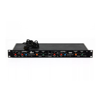
Dimensions
l-3/4"h x
19"w X 8"d
2
2
4
7
13
14
15