9
Since the 2-Series Equalizers consume a relatively small amount of power, the
units may be left on continuously.
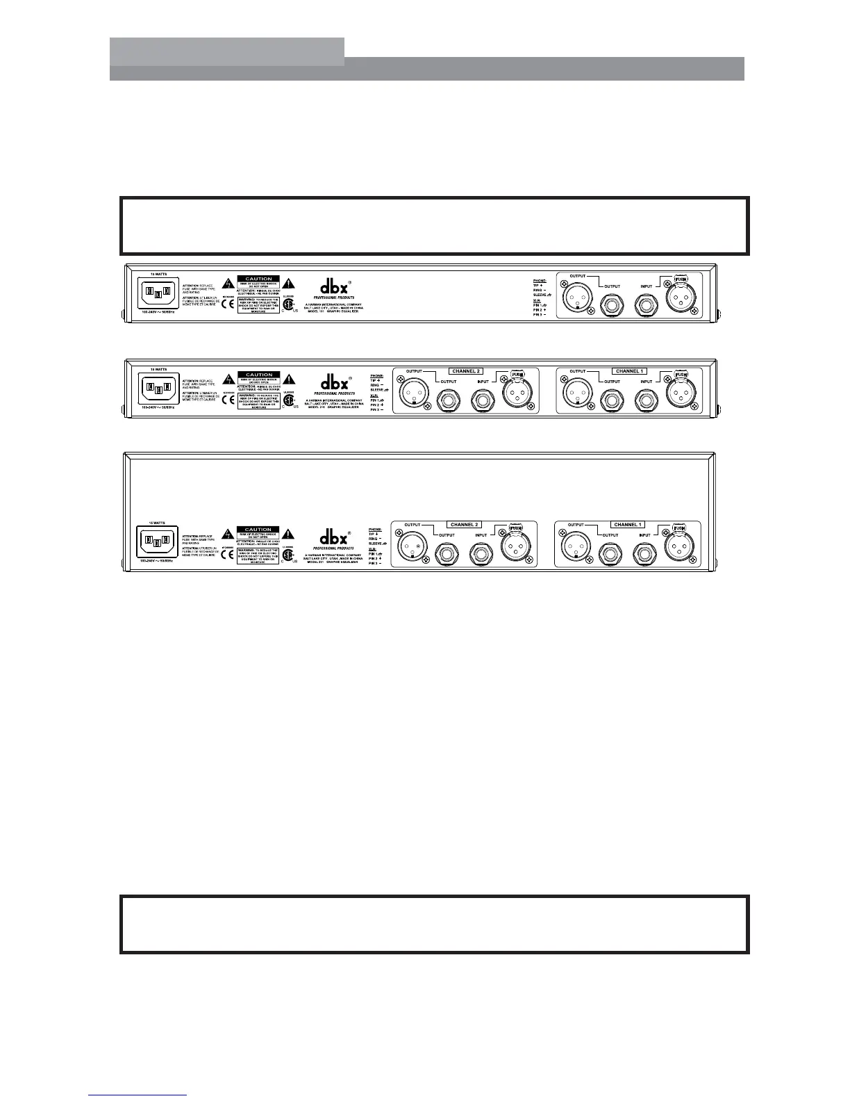
Section 4 - Rear Panel Descriptions
s
s
s
Power Cord Receptacle
Connects AC power to the equalizer.
Output Connectors
4WOTYPESOFOUTPUTCONNECTORSAREPROVIDEDFOROUTPUTCONNECTIONSMALE8,2TYPE
CONNECTORSANDTIPRINGSLEEVEPHONEJACKCONNECTORS
Input Connectors
4WOTYPESOFINPUTCONNECTORSAREPROVIDEDFORINPUTCONNECTIONSFEMALELOCKING8,2
TYPECONNECTORSANDTIPRINGSLEEVEPHONEJACKCONNECTORS4HEMAXIMUMINPUT
level that the equalizer can accept is typically +22 dBu (ref: 0.775Vrms).
Section 5 - Installation Considerations
Hookups and Cabling: The 2-Series Equalizers are designed for nominal +4 dBu levels.
The equalizers can be used with either balanced or unbalanced sources, and the out-
puts can be used with either balanced or unbalanced loads, provided the proper cabling
is used.
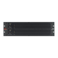
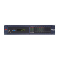
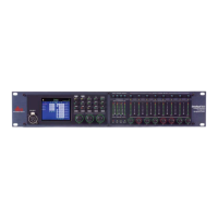
215s- Dual Channel 15 Band Graphic EQ
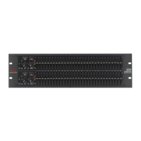
231s- Dual Channel 31 Band Graphic EQ
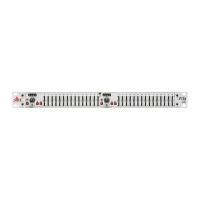
131s- Single Channel 31 Band Graphic EQ
User Manual
2-Series