22
7. INTERFACE SIGNALS AND CABLING
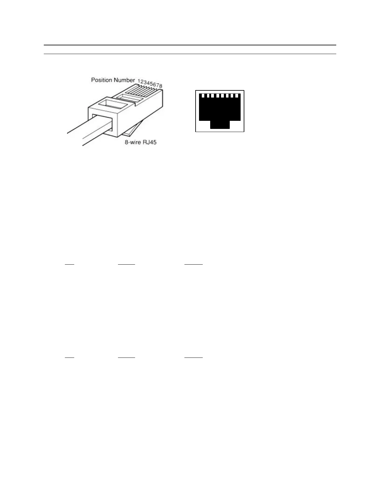
CONNECTOR AND PIN REFERENCE
RJ-45 Plug and Jack
PORT INTERFACE
Synchronous Port
The Synchronous port can be either RS-232 or RS-530 depending on the position of a jumper inside
the unit. This jumper (P7) is located behind the synchronous port connector (P8) and is defaulted to
RS-232. To change the port to RS-530, remove the two screws that hold the front panel in place and
remove the circuit board. Move the jumper to the position farthest away from the port connector
and reassemble the unit.
RS-232 (RJ-45)
Pin Signal In/Out
1 Receive Clock IN/OUT
2 Transmit Clock IN/OUT
3 Clear to Send IN
4 Signal Ground -----
5 Transmit Data OUT
6 Receive Data IN
7 Request to Send OUT
8 Data Carrier Detect IN
RS-530/422 (RJ-45)
Pin Signal In/Out
1 Transmit Data A (−) OUT
2 Transmit Data B (+) OUT
3 Receive Data A (−) IN
4 Receive Clock A (−) IN/OUT
5 Receive Clock B (+) IN/OUT
6 Receive Data B (+) IN
7 Transmit Clock A (−) IN/OUT
8 Transmit Clock B (+) IN/OUT
1 2 3 4 5 6 7 8