42
Be careful not to misalign the air shutters’ original position (unless readjusting). Lower the rear of
the burner into the cutouts on the support channel at the rear of the burner box. Make sure it is
level and does not rock. Light all of the burners and check that the flame is blue, stable and even.
If adjustments are necessary, refer to page 20. Complete these adjustments prior to cooking.
Replace internal lighting bulbs
Note: replacement bulbs are halogen, 12 volt, 10W max, T3 type
with a G4 bi-pin base.
1 Carefully remove the light bulb covers using your fingers or a
screwdriver.
2 Remove the light bulb and replace with a new bulb. Use gloves when
handling the
halogen bulbs as oils from finger-tips could damage the bulb.
3 Reinsert the light bulb cover. It should click back into place.
Cleaning light bulb covers
1 Carefully remove the light bulb covers using your fingers or a
screwdriver.
2 Clean the covers and remove grease with a cloth, warm water and
dishwashing liquid.
3 Reinsert the light bulb cover. It will click back into place.
IMPORTANT!
Halogen lamps are constructed of a glass bulb with a pressurized internal filament tube that operates
at high temperatures and could unexpectedly shatter. Should the outer bulb break, particles of
extremely hot glass could be discharged into the fixture enclosure and/or surrounding environment,
thereby creating a risk of personal injury or fire. When replacing the bulb, let the bulb cool, and assure
that power to the light has been turned off. Never allow the hot bulb to come into contact with water.
DO NOT TOUCH the light bulb when in use. It may be hot enough to cause injury.
IMPORTANT!
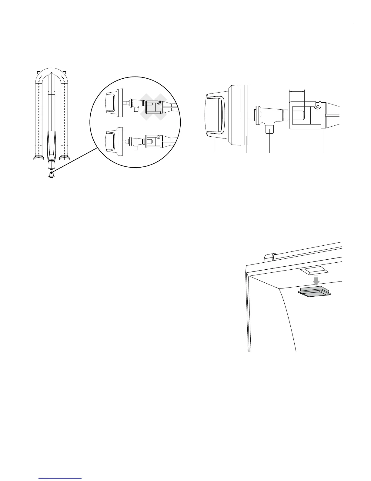
Center the burner onto the orifice properly before lighting the grill to prevent fire hazard or explosion.
KNOB CONTROL
VALVE
BURNER
VENTURI
VALVE
PANEL
⁄
”
MIN
Fig. 36 Fig. 37
REMOVE DRIP PAN TO VIEW CONNECTION
CARE AND MAINTENANCE
Burner alignment
 Loading...