20
INSTALLATION
Electrical Connection
Use only a Ground Fault Interrupter (GFI) protected circuit with this product.
An outdoor 120VAC 15A GFI electrical outlet should be installed by a qualified electrician either inside
the island enclosure for built-in units, or near the location where a free-standing unit will be used. For
built-in products, the supplied 12V transformer should be connected during installation.
Installation
The transformer must be secured below the product in a dry location away from any excessive heat.
Be sure to provide adequate access to facilitate service if the transformer or connections require
maintenance. For 2-pin connector models, multiple DCS Series 9 products may be connected to a single
transformer by purchasing and installing a DCS approved power splitter.
All units are supplied with a 12V power transformer to operate the products ignition and dial
illumination features. The transformer is sealed in a box with an attached power supply cord.
TO OUTLET TO OUTLET
Dial halos
When a dial is in use, an orange halo around that dial will illuminate. This will change from orange
to white if the dial is turned to off but another dial remains active. If all dials are turned OFF, all
halos will turn off. Multiple DCS Series 9 products may be linked together to allow for cross-product
halo illumination.
Linking 3-pin connector models
An approved DCS interconnectivity kit is required to enable this functionality.
Linking 2-pin connector models
An approved DCS retro-fit kit and the interconnectivity kit are required to enable this functionality.
The DCS retro-fit kit, interconnectivity kit and power splitter can be purchased separately from
your local DCS dealer. The retro-fit kit must be installed by a Fisher & Paykel trained and supported
service technician.
If the ignition or dial halos fail to operate, a connection may have come loose during installation or the
GFI may have tripped requiring a reset. Refer to the troubleshooting section further guidance.
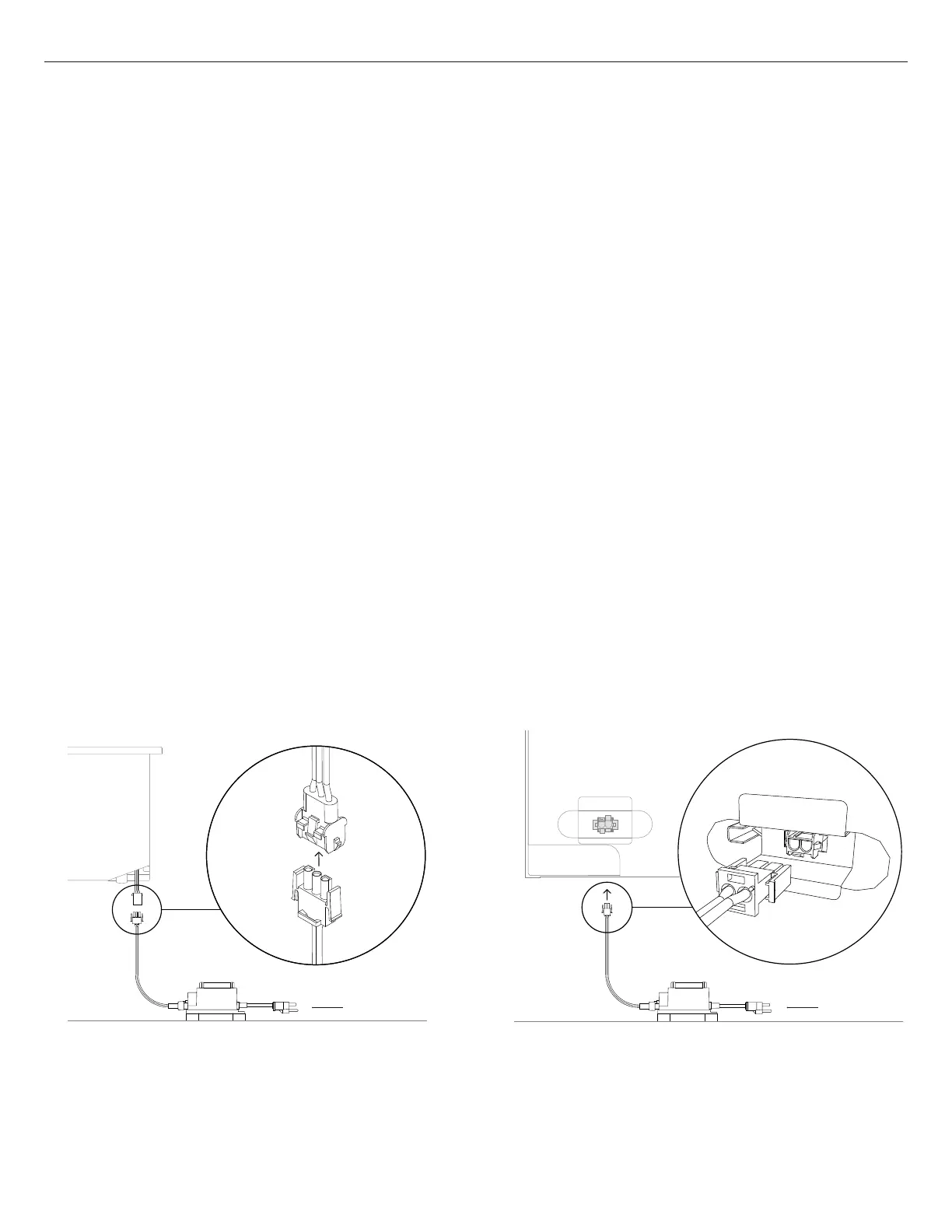
3-pin connector models
3-PIN MODELS - PROFILE VIEW
2-pin connector models
2-PIN MODELS - REAR VIEW
FIG. 13
 Loading...