14
INSTALLATION
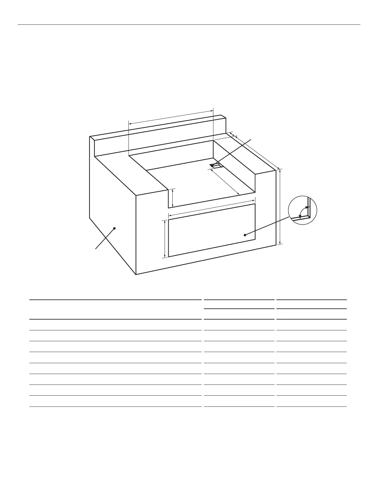
CAVITY DIMENSIONS
BE1-48R BE1-36R
Inches (mm) Inches (mm)
A
Maximum height of enclosure shell
35 1/2" (902) 35 1/2" (902)
B
Depth of enclosure shell
22 3/4" (578) 22 3/4" (578)
C
Minimum depth for hood swing
3 3/4" (95) 3 3/4" (95)
D
Width of enclosure cavity
45 3/4" (1162) 34 1/2" (876)
E
Height of enclosure cavity
10 1/8" (257) 10 1/8" (257)
f
Depth to gas supply opening
18 1/2" (470) 18 1/2" (470)
G
Height of opening for access doors/drawers
20" (508) 20" (508)
H
Width of opening for access doors/drawers
46" (1168) 34" (864)
Standard layout for non-combustible enclosure:
NOTE: If using a backguard
apron or rear wall, locate
electrical service on the
right hand side for rotisserie
motor connection
48" Models = 116,2 cm/45 3/4 "
36" Models = 87,6 cm/34 1/2"
9,5cm / 3 3/4" Min. for Lid
10,16 x 10,16cm
(4 x 4 ") opening
for gas supply
line
57,79 cm/22 3/4 "
46.36 cm/
18 1/2 "
25,72 cm/
10 1/8 "
64,5 cm
2
/10
"2
min
ventilation
left
64,5 cm
2
/10
"2
Min. ventilation
on the back side
2,54 cm/1 " min.
WARNING!
If installing the grill into
a non-combustible
enclosure, all
combustible
construction must still
be outside the 18 inch
clearance zone. If your
island is made of stucco
over the top of wooden
studs, the wood can not
be inside the 18 inch
clearance zone to
combustible, even
though the stucco is
what is touching the
grill area.
D
E
G
H
F
A
B
C
Built-in Construction Details
Standard layout for non-combustible cavity
IMPORTANT!
If installing the grill into a non-combustible enclosure, all combustible construction must still be
outside the 18" (457mm) clearance zone. If your island is made of stucco over the top of wooden
studs, the wood can not be inside the 18 inch clearance zone to combustible, even though the stucco
is what is touching the grill area.
Note: the enclosure should have
ventilation holes to prevent gas build-up
in the event of a leak. Refer to ANSI
Z21.58 Standard for Outdoor Cooking Gas
Appliances, Section 1.7 Enclosures For Self
Contained LP-Gas Supply Systems.
Note: 4x4” (102 x 102mm)
opening for gas supply line
FIG. 05
Note: the cut-out of each
corner should be a 90°angle
in order for the access doors/
drawers to fit properly.
 Loading...