18
Data Device Corporation
www.ddc-web.com
RDC-19220 SERIES
Q-05/05-0
Built-In-TestBIT21GroundGND20
Converter BusyCB22Analog GroundA GND19
MSBBit 123Enable MSBsEM18
Bit 924Current Set
R
C
17
Bit 225Sampling Set
R
S
16
Bit 10
26Power Supply-5 V15
Bit 327Signal Input-S14
Bit 1128Signal Output+SIN13
Bit 429Signal Input+S12
Bit 1230Signal Input-C11
Bit 531Signal OutputCOS10
Bit 1332Signal Input+C9
Bit 633Velocity OutputVEL8
Bit 1434Vel Sum Point-VSUM7
Bit 735Neg VCO Input-VCO6
Bit 1536-Reference Input-REF5
Bit 837+Reference Input+REF4
LSBBit 1638InhibitINH3
Enable LSBs (see
note)
EL39Resolution ControlB2
Power Supply+5 V40Resolution ControlA1
DESCRIPTIONNAME#DESCRIPTIONNAME
TABLE 8. RDC-19220 PINOUTS (40-PIN)
#
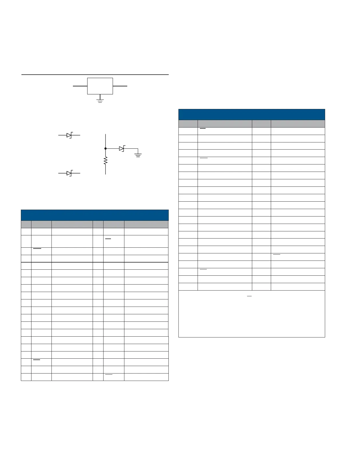
FIGURE 17. TYPICAL -5 VOLT CIRCUITS
TYPICAL -5 VOLT CIRCUITS
Since the 40-pin DDIP RDC-19220 does not have a pinout for
the -5 V inverter, it may be necessary to create a -5 V from other
supplies on the board. FIGURE 17 illustrates several possibili-
ties.
# NAME # NAME
1 EL 44 Bit 16 (LSB)
2 +5 V 43 Bit 8
3 A 42 Bit 15
4 B 41 Bit 7
5 INH 40 Bit 14
6 +REF 39 Bit 6
7 -REF 38 Bit 13
8 -VCO 37 Bit 5
9 -VSUM 36 Bit 12
10 VEL 35 Bit 4
11 +C 34 Bit 11
12 COS 33 Bit 3
13 -C 32 Bit 10
14 +S 31 Bit 2
15 SIN 30
Bit 9
16 -S 29 Bit 1 (MSB)
17 -5 V 28 CB
18 RS 27 BIT
19 RC 26 +5C (+5 V)
20 EM 25 +CAP
21 A GND 24 GND
22 -5C (-5 V) 23 -CAP
NOTES:
1. When -5 V is applied to pin 1 (EL), Converter Busy (CB) becomes
Zero index (ZI).
2. When using the built-in -5 V inverter: connect pin 2 to 26, pin 17 to
22, and a 10 µF/10 Vdc capacitor from pin 23 (negative terminal) to
pin 25 (positive terminal). Connect a 47 µF/10 Vdc capacitor from -5
V to GND. The current drain from the +5 V supply doubles. No exter-
nal -5 V supply is needed.
TABLE 9. RDC-19222 PINOUTS (44-PIN, +5 V ONLY)
PINOUT FUNCTION TABLES BY MODEL NUMBER
The TABLES 8 and 9 detail pinout functions by the DDC model
number.
The RDC-19220 has differential inputs but requires both ±5 V
power supplies.
The RDC-19222 has differential inputs and can be used with the
+5 V only option.
 Loading...