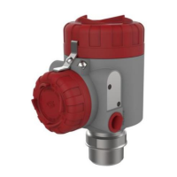
This document provides instructions for the TRG808X Series 80GHz Radar Level Meter, manufactured by Dandong Top Electronics Instrument (Group) Co., Ltd. The device is designed for accurate level measurement in various industrial applications.
Function Description
The TRG808X radar level meter utilizes Frequency Modulated Continuous Wave (FMCW) technology. It transmits a high-frequency FM radar signal through an antenna, which propagates at the speed of light. When this signal encounters the surface of the measured medium, part of its energy is reflected back and received by the same antenna. The frequency difference between the transmitted and received signals is directly proportional to the measured distance, allowing the device to calculate the distance from the antenna to the medium's surface. The device can also operate by transmitting very short microwave pulses with very low energy, where the time interval between the transmitted and received pulses is proportional to the distance.
The instrument is designed to provide real-time measurement of process quantities such as level, air height, or distance. It features a measurement interface to display current operational status and measurement data, an echo interface to visualize the echo situation, and a setup interface for configuring various system parameters.
Important Technical Specifications
The TRG808X series includes several models (TRG8081, TRG8082, TRG8083, TRG8084, TRG8085), each with specific antenna structures and performance characteristics:
- Power Supply: All models operate on 12 ~ 28V DC.
- Output Signal: All models provide 4 ~ 20mA + HART and RS485 + Modbus RTU outputs.
- Ambient Temperature: -40°C ~ +70°C for all models.
- IP Rating: IP67 for all models, indicating protection against dust and temporary immersion in water.
- Housing Material: Aluminum alloy for all models.
- Explosion-proof Certification: The device passes national level explosion-proof certification, including intrinsically safe (Ex ia IIC T1~T5/T6 Ga; Ex iaD 20 T85°C) and intrinsically safe and explosion-proof composite types (Ex d ia [ia Ga]IIC T1 ~ T5/T6 Gb; Ex tD A21 T105°C/T85°C).
- Implementation Standards: Complies with JB/T 13252-2017 Microwave (Radar) Level Meters.
Model-Specific Specifications:
-
TRG8081 (Small Lens Antenna):
- Measuring Range: 0.08m ~ 10m / 0.08m ~ 30m
- Accuracy: ±1mm / ±1mm
- Beam Angle: 8°
- Process Temperature: -40 ~ 85°C
- Process Pressure: -0.1 ~ 2.5 MPa
-
TRG8082 (Standard Lens Antenna):
- Measuring Range: 0.08m ~ 10m / 0.08m ~ 30m / 0.3m ~ 60m / 0.3m ~ 120m
- Accuracy: ±1mm / ±1mm / ±3mm / ±5mm
- Beam Angle: 3°
- Process Temperature: -40 ~ 200°C
- Process Pressure: -0.1 ~ 2.5 MPa
-
TRG8083 (Anti-corrosion Antenna):
- Measuring Range: 0.08m ~ 10m / 0.08m ~ 30m / 0.3m ~ 60m / 0.3m ~ 120m
- Accuracy: ±1mm / ±1mm / ±3mm / ±5mm
- Beam Angle: 3° / 8°
- Process Temperature: -40 ~ 150°C
- Process Pressure: -0.1 ~ 2.5 MPa
-
TRG8084 (Universal Blow-up Antenna):
- Measuring Range: 0.08m ~ 10m / 0.08m ~ 30m / 0.3m ~ 60m / 0.3m ~ 120m
- Accuracy: ±1mm / ±1mm / ±3mm / ±5mm
- Beam Angle: 3°
- Process Temperature: -40 ~ 200°C
- Process Pressure: -0.1 ~ 0.3 MPa
-
TRG8085 (High Temperature and High Voltage Antenna):
- Measuring Range: 0.08m ~ 10m / 0.08m ~ 30m / 0.3m ~ 60m / 0.3m ~ 120m
- Accuracy: ±1mm / ±1mm / ±3mm / ±5mm
- Beam Angle: 3°
- Process Temperature: -40 ~ 1000°C
- Process Pressure: -0.1 ~ 10 MPa
Usage Features
- Installation: The device requires careful installation, ensuring it is at least 200 mm away from the vessel wall. For conical vessels with flat tops, the optimal mounting position is at the center to measure the entire vessel bottom. In outdoor or wet environments, the cable sealing sleeve must be tightened, and the cable bent downwards at the entry point to prevent moisture ingress. The vessel receiver should be long enough for the antenna end to extend as far as possible into the tank.
- Electrical Wiring: The device supports both 4-20mA two-wire system and RS485 output signals.
- For 4-20mA, Terminal 1 connects to 24VDC negative, Terminal 2 to 24VDC positive. Terminal 3 is for loop current testing in conjunction with Terminal 2.
- For RS485, Terminal 1 connects to 24VDC negative, Terminal 2 to 24VDC positive, Terminal 6 to RS485 A, and Terminal 5 to RS485 B.
- Configuration: The instrument features a user-friendly interface with four keys (ESC, UP, DN, ENT) for navigation and configuration.
- Measurement Interface: Displays real-time value, damping value (smoothed real-time value), internal component temperature, model number, communication status, units, current value (theoretical 4-20mA output), and fault codes.
- Echo Screen: Shows echo intensity, real-time value, and range. It allows switching return intensity display units and showing/hiding threshold curves. Return strength indicates the maximum return strength; a good metal reflector should yield around 90dB, while less than 30dB indicates a weak signal.
- Setup Screen (Basic Settings): Includes "High-Low Adjustment" to define full and empty material positions, and "Blind Zone Setting" to ignore echoes within a specified near-end area, preventing interference. "Range Setting" limits the algorithm area to avoid multiple reflections and out-of-range interference, ideally 1-2m greater than the actual tank height.
- Professional Menu Settings (False Echo Learning): This feature allows the device to learn and screen out false echoes from known obstacles or background noise by forming a screening curve (threshold curve TVT). Users can choose to perform learning over the full range, a selected area, or an excluded area.
- Safety Precautions: It is crucial to ensure a safe and reliable power supply, correct polarity, and proper grounding. When installing, avoid placing the radar level meter directly above material flow; if unavoidable, use a wave guide or bypass tube. The radar antenna must be perpendicular to the measured medium's surface. After configuration, the display and power supply covers must be tightened to prevent water and moisture ingress.
Maintenance Features
- Quality Assurance: Dandong Top Electronics Instrument (Group) Co., Ltd guarantees products against defects in materials and manufacturing for one year from the factory departure date. Repairs or replacements are provided free of charge for qualifying claims.
- Troubleshooting: The instrument displays fault codes on the LCD in case of failure. The manual provides a table of fault codes and their meanings, such as "No valid echoes found," "Communication exception," "Abnormal current output," and "Processor hardware errors," to aid in diagnosis.
- Disassembly: Before disassembling the instrument, users are warned to be aware of dangerous process conditions like pressure, high temperature, or corrosive/toxic media in the container.
- Waste Disposal: Follow current regional regulations for waste disposal.
- Product Modification: Unauthorized modification or alteration of the product is strictly prohibited for safety reasons. Only manufacturer-specified accessories should be used for repair or replacement.
- Documentation: The product instructions should be kept near the instrument for easy reference. The manual can also be downloaded from www.ddtop.com. Failure to follow the manual may compromise the instrument's protection.