12 / 18
Figure10 Schematic Diagram of Container Receiver
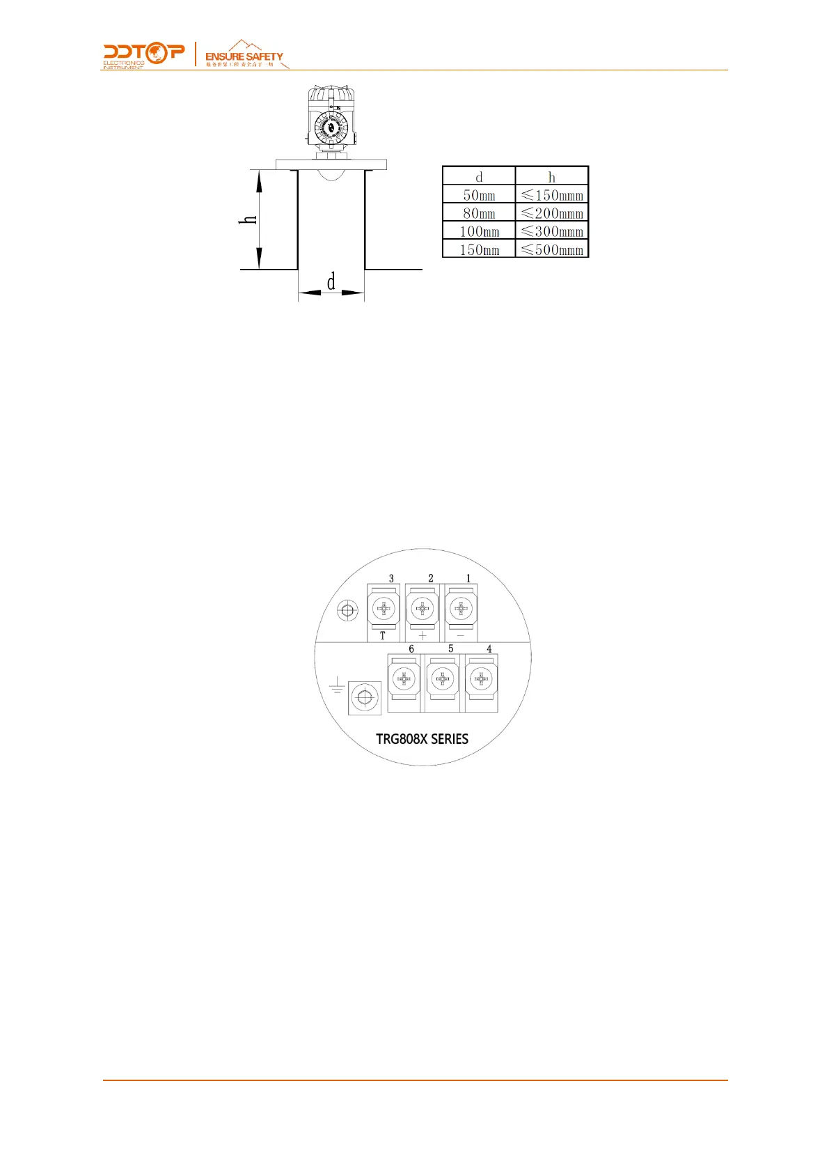
7 Electrical Wiring
Output signal: 4 to 20mA two-wire system
Terminal 1: Connected to the negative terminal of 24VDC.
Terminal 2: Connected to the positive terminal of 24VDC.
Terminal 3: Loop current test, used in conjunction with terminal 2. Terminal 2 and 3 are
connected to an ammeter to measure the loop output current.
Figure 11 4~20mA Wiring Diagram
Output signal: RS485
Terminal 1: Connected to 24VDC negative.
Terminal 2: Connected to 24VDC positive.
Terminal 6: Connected to RS485 A.
Terminal 5: Connected to RS485 B.
 Loading...