4.2
SWING GATES CONFIGURATION
ELECTRICAL CONNECTIONS
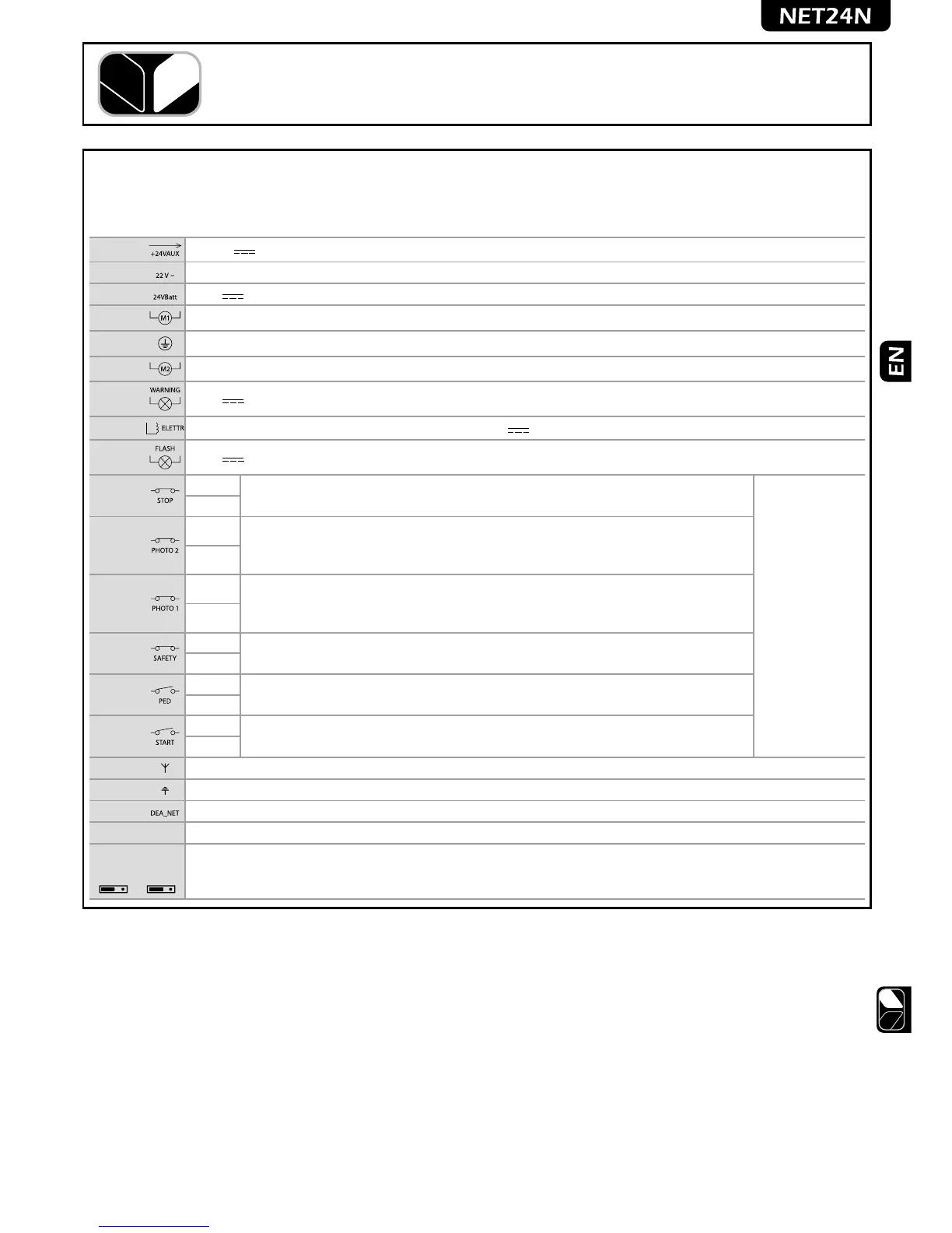
Execute the wiring following the directions of table 1 and diagrams on page 46.
Table 1 “terminal board connections”
1-2 +24 V power supply output for auxiliary devices 200mA
3-4
22 V ~ transformer power supply input
5-6
24 V battery power supply or photovoltaic accumulator Green Energy input (follow carefully polarity indications).
7-8
Operator 1 output
9
Connection of motors metallic parts
10-11
Operator 2 output (if present)
12-13 24 V max 15 W output for open gate fix/flashing warning light (if P052=0/1) or courtesy light (if P052>1)
14-15
Electric-lock output max 1 art. 110 (if P062=0) or 24V output max 5W configurable (if P062≠0)
16-17 24 V Flashing light output max 15W art. Lumy/24A/S
18-19
18 - N.C.
Input 6 STOP. In case of intervention, it stops the movement of both motors during any
operation. If unused, short circuit.
If the installation requires different commands
and / or additional to the standard, you can
configure each input to the required rate.
Refer to Chapter
“Advanced Programming”.
19 - Com
20-21
20 - N.C.
Input 5 PHOTO 2. When enabled (see parameter P051 in the table), activation of PHO-
TO 2 provokes: an inversion of direction (during closing), the arrest of the movement
(during opening), prevent the start (gate closed). If unused, short circuit.
21 - Com
22-23
22 - N.C.
Input 4 PHOTO 1. When enabled (see parameter P050 in the table), activation of PHO-
TO 1 provokes: an inversion of direction (during closing), the arrest of the movement
(during opening), prevent the start (gate closed). If unused, short circuit.
23 - Com
24-25
24 - N.C.
Input 3 SAFETY. If activated, it causes the inversion. See P055 and P056 on the parame-
ters table. If unused, short circuit.
25 - Com
26-27
26 - N.O.
Input 2 PED. If activated, it opens motor nr. 1 only.
27 - Com
28-29
28 - N.O.
Input 1 START. In case of intervention it provokes: the operator opening or closing. It may
operate as “inversion” mode (P49=0) or “step by step” mode (P49=1).
29 - Com
30
Aerial signal input
31
Ground aerial input
32-33
DEA_NET net input (unused at the moment)
CON 1 230 V ~ ±10% (50/60 Hz) power supply input
J5 J9
Encoder selection Jumper:
•A position = operators with encoder (remind to set P029=0)
•B position = operators without encoder (remind to set P029=1)
AB AB
 Loading...