EN-5
5 ELECTRICAL CONNECTIONS
Execute the wiring following the directions of table 1 and diagrams.
WARNING For adequate electrical safety, keep low safety voltage wires (controls, electro-locks, antenna, auxiliary power) clearly separate
from 230V ~ power wires (minimum 4 mm in air or 1 mm via supplementary insulation) placing them in plastic raceways and securing
them with adequate clamps near terminal boards.
WARNING For connection to the mains, use a multipolar cable having a minimum section 3x1,5 mm² and complying with the current
regulations. For connecting the motors, use a minimum cross section 1,5 mm² cable and complying with the current regulations. As
an example, if the cable is out side (outdoor), must be at least equal to H07RN-F, whereas if it (in a raceway), must be at least equal to
H05VV-F.
WARNING All wires must be striped and unsheathed in the immediate vicinity of terminals. Keep wires slightly longer to subsequently
eliminate any excess.
WARNING To connect the encoder to the control panel, use only a dedicated cable ≥ 3x0.25mm
2
.
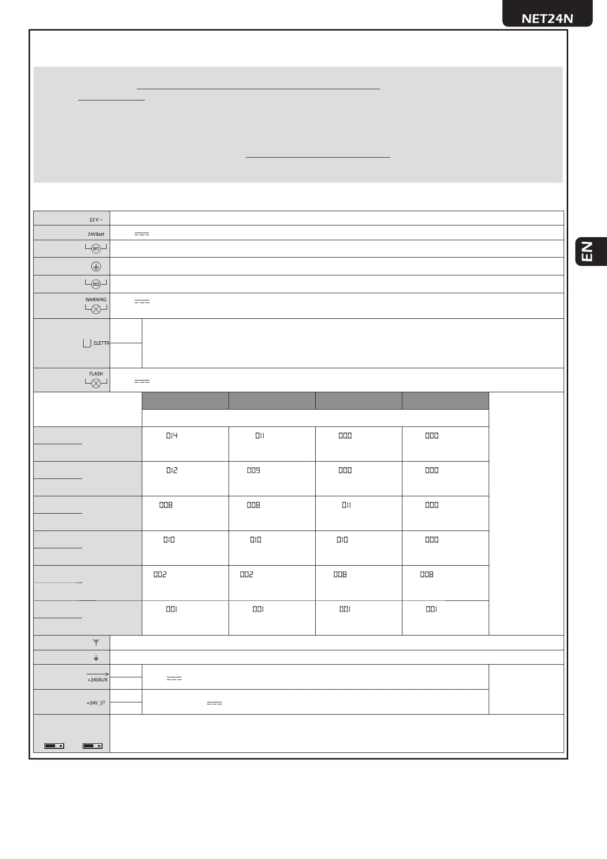
Table 1 “terminal board connections”
3-4 22 V ~ transformer power supply input
5-6 24 V battery power supply or photovoltaic accumulator Green Energy input (follow carefully polarity indications).
7-8
Operator 1 output
9
Connection of motors metallic parts
10-11
Operator 2 output (if present)
12-13
24 V max 15 W output for open gate fi x warning light (if P052=0), fl ashing (if P052=1) or courtesy light (if
P052>1)
14-15
14 (-)
“Boost” output for electric-lock, max 1 x art. 110 (if P062=0), 24V pulse output, max 5W (if P062=1), step
by step (if P062=2), electro-brake output for not self-locking operators (if P062=3), output for electric-lock
power supply via external relay (if P062=4), output for electro-magnets power supply for barriers (ifP062=5)
or temporized output (if P062>5).
15 (+)
16-17 24 V Flashing light output max 15W art. LED24AI
TYPE 00 TYPE 01 TYPE 02 TYPE 03
If the installation requires different commands and / or ad-
ditional to the standard, you can confi gure each input to the
required rate.
Refer to Chapter
“Advanced Programming”.
If unused, short circuit
18 - IN_6
Input 6
(FCC 1) (STOP) (NONE) (NONE)
19 - Com
N.C. N.C. N.O. N.O.
20 - IN_5
Input 5
(FCA 1)
(PHOTO 2)
(NONE) (NONE)
21 - Com
N.C. N.C. N.O. N.O.
22 - IN_4
Input 4
( PHOTO 1) (PHOTO 1) (STOP) (NONE)
23 - Com
N.C. N.C. N.C. N.O.
24 - IN_3
Input 3
(SAFETY) (SAFETY) (SAFETY) (NONE)
25 - Com
N.C. N.C. N.C. N.O.
26 - IN_2
Input 2
(PEDESTRIAN) (PEDESTRIAN) (PHOTO 1) (PHOTO 1)
27 - Com
N.O. N.O. N.C. N.C.
28 - IN_1
Input 1
(START) (START) (START) (START)
29 - Com
N.O. N.O. N.O. N.O.
- Aerial signal input
-
Ground aerial input
32-33
32 (+)
24 V power supply output for auxiliary devices
(AUX + ST)
=
max 200mA
33 (-)
1-2
1 (-)
Stabilized 24 V power supply output for tested safety devices
2 (+)
J5 J9
Encoder selection Jumper:
•A position = operators with encoder (remind to set P029=0)
•B position = operators without encoder (remind to set P029=1)
AB AB