O L I 6 0 0
Operating instructions and warnings
12
RESPONSIBILITIES OF THE INSTALLER
Remember that anyone who sells and/or motorises doors/gates becomes the manufacturer of the automatic door/gate machi-
ne and must therefore prepare and conserve a technical folder that contains the following documents (see Machinery Directive
Enclosure V):
• Assemblydrawingoftheautomaticdoor/gate;
• Electricalconnectionandcontrolcircuitwiringdiagram;
• Riskanalysisincluding:alistoftheessentialsafetyrequirementsprovidedinMachineryDirectiveEnclosureI;alistoftherisks
posed by the door/gate and the description of the solutions adopted.
• Keeptheseoperatinginstructionsinasafeplacetogetherwiththeinstructionsforalltheothercomponents;
• Preparetheseoperatinginstructionsandgeneralsafetywarnings(forthecompletionoftheseoperatinginstructions)anddeli-
ver a copy to the final user;
• Filloutthemaintenanceregisteranddeliveracopytothefinaluser;
• DrafttheCEdeclarationofconformityanddeliveracopytothefinaluser;
• FilloutthecompleteCElabelorplateandapplyittothedoor/gate.
Note: The technical folder must be conserved for inspection by the competent national authorities for at least ten years from
the date construction of the automatic door/gate.
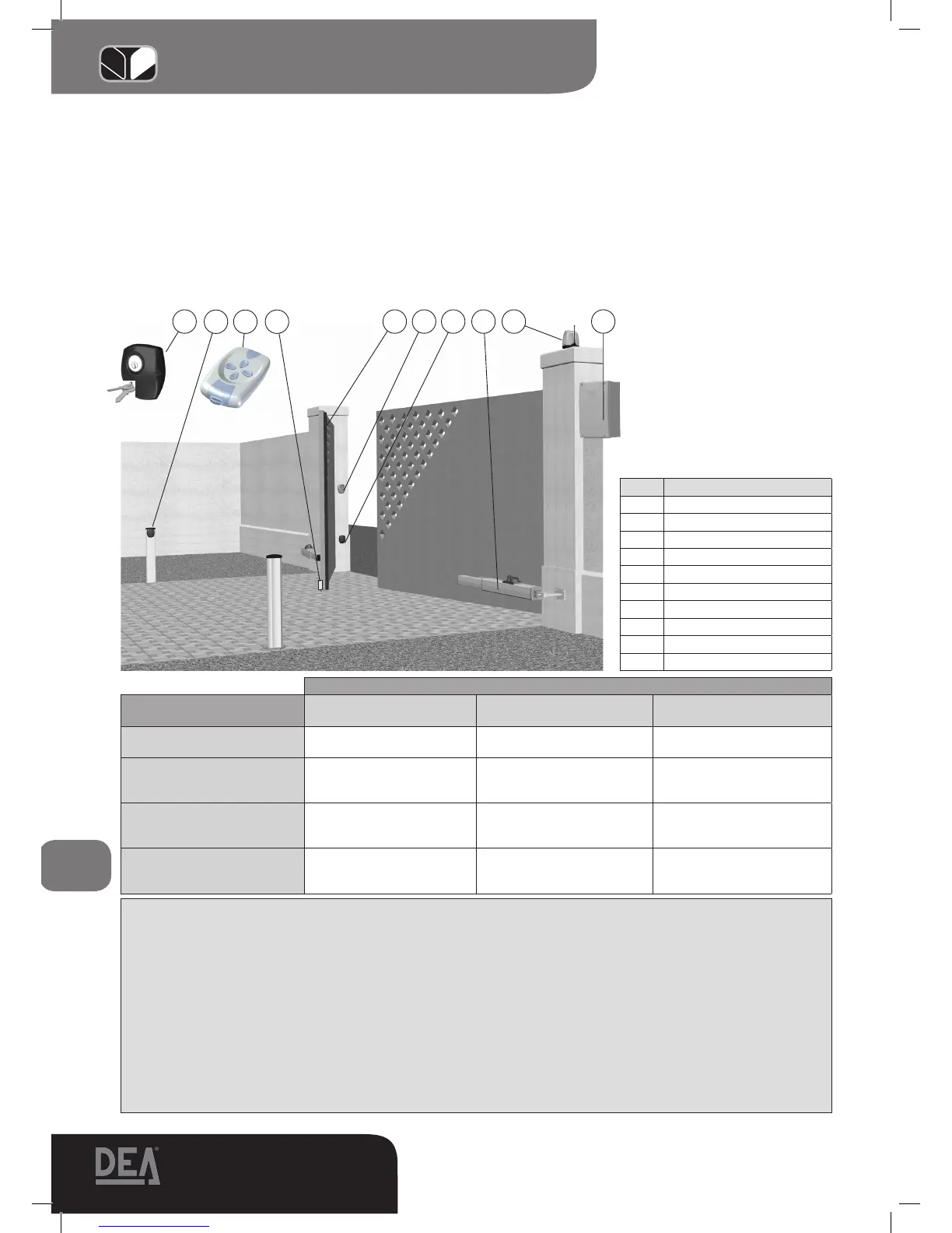
1 5 6 7 8 9
2 3
4
10
Pos. Description
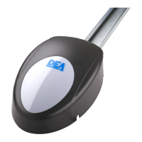
1 102 Lux keyswitch
2 Pilly 60 column
3 Remote-control
4 Electric lock
5 Safety edge
6 FLIC/rad digital keypad
7 104 Lux series photocells
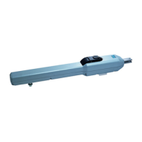
8 OLI 600
9 Lumy flashing light
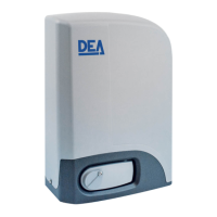
10 Control box
Type of use
Type of control
Informed users
(private areas)
Informed users
(public areas)
Uninformed users
Person-present control Pushbutton control Pushbutton control with key
The person-present control is
not possible
Pulse control with the gate in
sight
Force limitation
or
presence detectors
Force limitation
or
presence detectors
Force limitation
and photocells
or presence detectors
Pulse control with the gate not
in sight
Force limitation
or
presence detectors
Force limitation
and photocells
or presence detectors
Force limitation
and photocells
or presence detectors
Automatic control
(i.e. control with
timed closing)
Force limitation
and photocells
or presence detectors
Force limitation
and photocells
or presence detectors
Force limitation
and photocells
or presence detectors
“EXAMPLE OF TYPICAL INSTALLATION” picture
The risk of crushing can also arise in the area between the gate being opened and the wall or other construction behind it. F10
on Page 32 provides the measurements that must be respected whenever measures are not taken to limit the impact force or whe-
never presence detection systems are not used.
6.3 Impact in the opening/closing area
In order to avoid crushing by the gate wing in the closing area, install a pair of photocells (A) (recommended height: 500 mm)
in order to detect the presence of the test parallelepiped (B) (height: 700 mm) positioned as shown in F11 on Page 32.
Note. The presence detection test sample is a parallelepiped with 3 sides with light-coloured reflecting surfaces and 3 sides with
dark-coloured, opaque surfaces.
In order to further reduce the risk of impact with the gate wing in the opening area, an extra pair of photocells (C) (recommended
height: 500 mm) can be installed for the detection of the presence of the test parallelepiped (D) (height: 700 mm) positioned as
shown in F11 on Page 32.