Do you have a question about the Dedenbear Thunder T1 and is the answer not in the manual?
Mounting and wiring guidelines for the THUNDER unit, ensuring proper placement and connections.
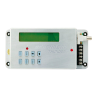
Overview of the buttons on the THUNDER unit and their functions for quick reference.
Detailed explanation of each button's function on the THUNDER delay box.
Explanation of the PRO/FULL feature for switching between two distinct setting groups.
Details on the four delay box modes: Delay, Crossover, Interface, and Cross Talk.
Description of the 'ready to run' screen displaying current settings and status.
How to set the primary delay time for launching the car.
Setting the secondary delay for specific modes like Cross Talk.
Entering opponent's and own dial-in times for specific modes.
Setting delay for bottom bulb release in specific modes like Interface and Cross Talk.
Adjusting crossover compensation time for late lights.
Adding or subtracting time from delay after transbrake release.
Time the box pauses before transbrake application.
Time the transbrake is locked out to prevent re-application.
Comparison of factory default settings for PRO and FULL modes.
Definitions for Reset/Recall, ARP, Last Chance, How Late, Skip Recall, Dial-ins Incorrect, Line Lock.
Describes the four methods to exit setup menus and return to run mode.
Information on memory, battery chargers, temperature effects, and welding precautions.
How the THUNDER prevents red lights on a pro tree.
Using the THUNDER for consistent launches off the top amber bulb.
Launching off opponent's top bulb when you are the faster car.
Taking two hits at the tree and launching on the quicker release.
Taking two hits at your tree for different amber lights.
How to compensate for early (red) lights by adding delay.
How to compensate for late (green) lights by subtracting delay.
Instructions for wiring the 12v power supply and ground connections.
Wiring the transbrake solenoid and launch button.
Wiring for the optional Skip button.
Wiring the line lock output to the solenoid.
Connecting accessories that require a transbrake trigger signal.
Instructions for wiring the remote display unit and its connection to the THUNDER.
Details on warranty period, repair/replacement, and limitations.
| Brand | Dedenbear |
|---|---|
| Model | Thunder T1 |
| Category | Recording Equipment |
| Language | English |