Management Procedure 2585 Rev. F
3
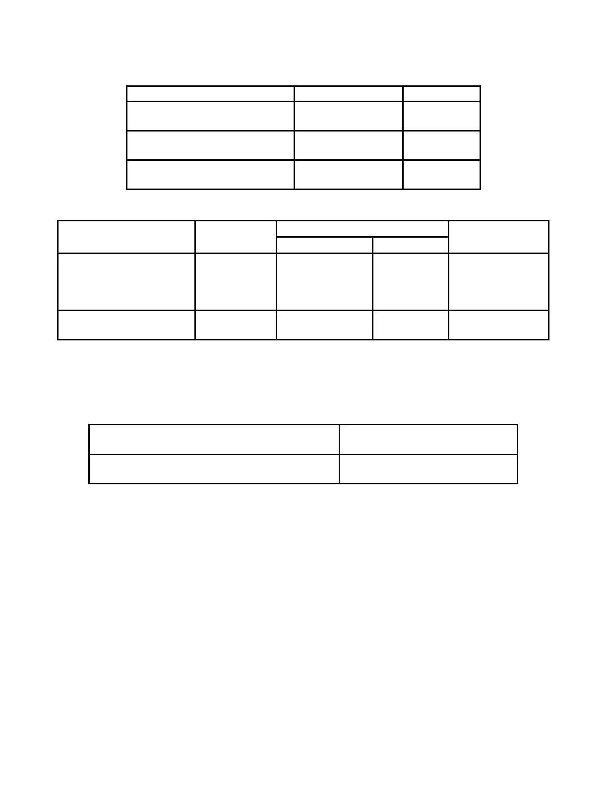
Table 2-2 Minimum Use Specification
Model Range Accuracy
UTG, UTG-STD, UTG-C
UTG-CA, UTG-CLF, UTG-CX
1.0 - 125 mm
(0.040 - 5.000”)
± 0.008 mm
(± 0.00025”)
UTG-M & UTG-ME
2.5 - 125 mm
(0.100 - 5.000”)
± 0.008 mm
(± 0.00025”)
UTG-P
0.200 – 12.000 mm
(0.008 – 0.472”)
± 0.003 mm
(± 0.0001”)
Table 2-3 Actual Equipment Specification
UUC Model Equipment
Generic Name
Actual Equipment Specifications Manufacturer &
Model Applicable
Range Accuracy
UTG, UTG-STD, UTG-C
UTG-CA, UTG-CLF,
UTG-CX, UTG-M &
UTG-ME
Step Blocks
2.50 - 12.50 mm
(0.100 - 0.500”)
± 0.005 mm
(± 0.00020”)
PH Tool Custom
5 Step Block
UTG-P Step Blocks
0.50 - 2.50 mm
(0.020 – 0.098”)
± 0.005 mm
(± 0.00020”)
PH Tool Custom
5 Step Block
Caution: The instructions in this Calibration Procedure relate specifically to the equipment and
conditions listed in this section. If other equipment is substituted, the information and
instructions must be interpreted accordingly.
Table 2-4 Calibration Environmental and Warm Up Requirements
Measurement Standards & Support Equipment
Environmental Requirements:
Temperature: 23 ± 5° C.
Relative Humidity: Less than 95%
Measurement Standards & Support Equipment
Warm-up and Stabilization Requirements:
None
3 Preliminary Operations
Note: Review the entire document before starting the calibration process.
3.1 Visual Inspection
3.1.1 Visually inspect the UUC for:
• Probe tip wear or damage
• Other damage or wear
• Proper identification
3.1.2 Damage or excess wear shall be repaired prior to beginning the calibration process.
3.2 Gage Reset
 Loading...