a. Connect port 1 on SP A in the bottom slot in the DPE to port A on the link
control card A (LCC A) at the bottom of the DAE. [
]
b. Connect port 1 on SP B in the top slot in the DPE to port A on the link
control card (LCC B) at the top of the DAE. [
]
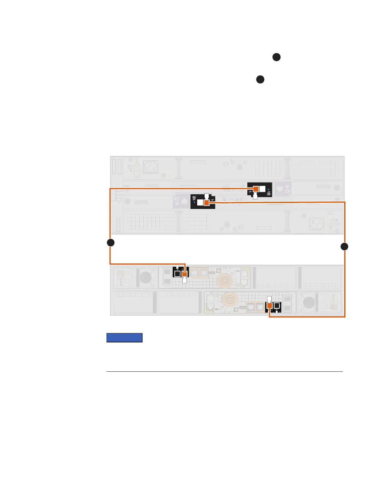
Cabling the second optional DAE to extend back-end bus 0
Connect the second optional expansion DAE to the DPE expansion port 0 to extend
back-end bus 0 (BE0) and designate this DAE as enclosure 1 of this bus. We refer to
the address of this enclosure as BE0 EA1 (0_1).
Use the following illustration to complete this cabling task:
Figure 27 Example: DPE to 15-drive DAE
0
1
x4
0
1
x4
x4 x4
A
B
A
B
A
B
AB
x4
x4
1
2
When cabling the 15-drive DAE LCC SAS ports, ensure that the cables do not overlap
behind the DAE. The illustration above demonstrates the proper method for cabling to
the DAE LCC SAS ports.
Procedure
1. Label a pair of mini-SAS HD cables using the orange labels shown here.
Cable and power up your DAE components
Cabling the second optional DAE to extend back-end bus 0 57