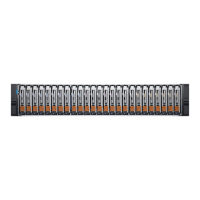
Do you have a question about the Dell EMC Unity 450F and is the answer not in the manual?
Details the sequence of actions for system installation, including optional Disk Array Enclosures (DAEs).
Details the process of installing the Disk Processor Enclosure (DPE) into a server rack.
Describes the procedure for securely mounting the Disk Processor Enclosure (DPE) onto the installed rack rails.
Provides instructions for powering up the Disk Processor Enclosure (DPE) and its components.
Describes how to use DHCP to automatically assign an IP address to the storage system's management port.
Explains how to use the Connection Utility to manually assign a static IP address for management.
Illustrates connecting DAEs to DPE SAS modules for back-end buses 2 through 5.
Contains a worksheet to collect and record system configuration information for setup.
| Model | Unity 450F |
|---|---|
| Category | Storage |
| Maximum Raw Capacity | 1.2 PB |
| Form Factor | 2U |
| Drive Types Supported | SSD |
| Processor | Intel Xeon |
| Processors | 2 |
| Memory | 64 - 256 GB |
| RAID Support | Yes |
| Warranty | 3 years |
| Supported Protocols | iSCSI, NFS, SMB |
| Drives | 2.5-inch SSD |
| Connectivity | 10GbE |
| Host Connectivity | iSCSI, NFS, SMB |
| RAID Levels Supported | RAID 0, 1, 5, 6, 10 |
| Operating System | Dell EMC Unity Operating Environment |
| Power Supply | Redundant power supplies |


