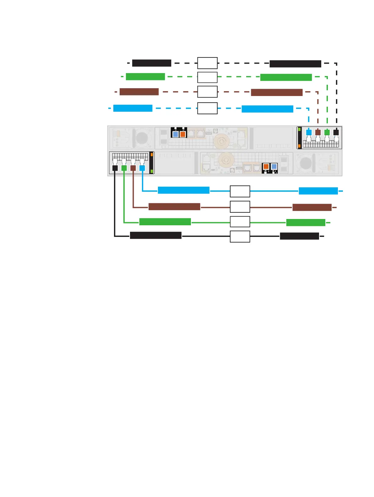
Figure 28 Bus 2, Bus 3 , Bus 4, and Bus 5 enclosure 0 SAS cabling
0 1 2 3
0 1 2 3
SP A A0 PORT 0
SP A A0 PORT 1
SP A A0 PORT 2
SP A A0 PORT 3
0
1
x4
0
1
x4
LCC A Port A
LCC A Port A
LCC A Port A
LCC A Port A
SP B B0 PORT 0
SP B B0 PORT 1
SP B B0 PORT 2
SP B B0 PORT 3
LCC B Port A
LCC B Port A
LCC B Port A
LCC B Port A
2_0
3_0
4_0
5_0
2_0
3_0
4_0
5_0
l
2_0 side A, black, SP A B0 port 0 to DAE <
w
> LCC A port A
l
2_0 side B, black, SP B B0 port 0 to DAE <
w
> LCC B port A
l
3_0 side A, green, SP A B0 port 1 to DAE <
x
> LCC A port A
l
3_0 side B, green, SP B B0 port 1 to DAE <
x
> LCC B port A
l
4_0 side A, brown, SP A B0 port 2 to DAE <
y
> LCC A port A
l
4_0 side B, brown, SP B B0 port 2 to DAE <
y
> LCC B port A
l
5_0 side A, cyan, SP A B0 port 3 to DAE <
z
> LCC A port A
l
5_0 side B, cyan, SP B B0 port 3 to DAE <
z
> LCC B port A
For each new BE2-BE5:
Procedure
1. Label a pair of mini-SAS HD cables using the appropriate labels (black, green,
brown, or cyan) shown here.
Cable and power up your DAE components
Cabling the DPE SAS module ports to create back-end buses 2 through 5 59