9. Remove the memory modules.
10. Remove the solid-state drive.
11. Remove the WLAN card.
12. Remove the heat-sink and fan assembly.
13. Remove the processor.
About this task
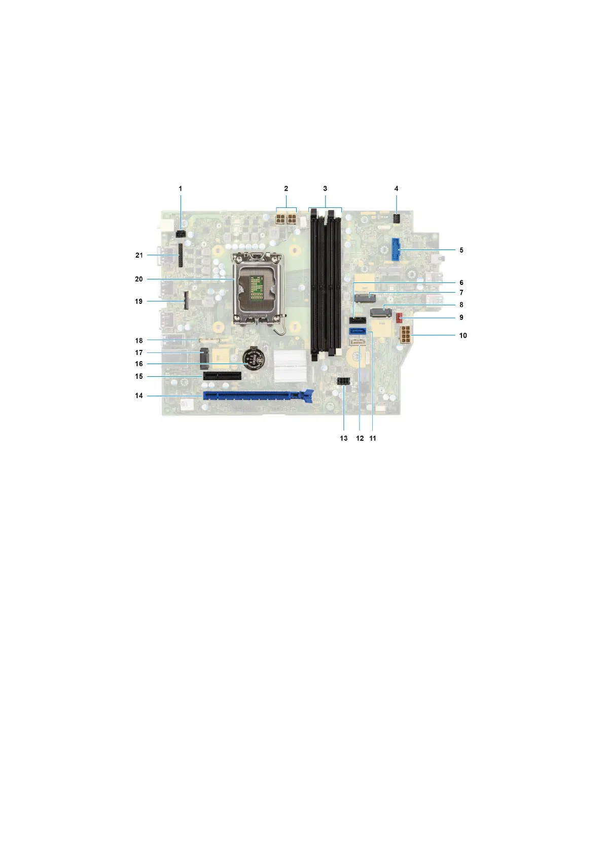
The following image indicates the connectors on your system board.
1. Intrusion-switch cable 2. Processor-power cable
3. UDIMM slots
From the left (a>b>c>d):
DIMM 3
DIMM 1
DIMM 4
DIMM 2
4. Power-button cable
5. SD-card reader slot 6. Hard-drive data cable (SATA 0)
7. M.2 WLAN slot 8. M.2 2230/2280 solid-state drive slot
9. Chassis-fan cable 10. ATX system power connector
11. Hard-drive data cable (SATA 1) 12. Optical-drive/hard-drive data cable (SATA 2)
13. SATA power cable 14. PCIe x16 slot (SLOT 2)
15. PCIe x4 slot (SLOT 4) 16. Coin-cell battery socket
17. M.2 2230 solid-state drive slot 18. Type-C cable
19. Video cable 20. Processor socket
21. I/O cable
The following images indicate the location of the system board and provide a visual representation of the removal procedure.
102
Rimozione e installazione di unità sostituibili sul campo (FRU)