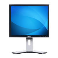
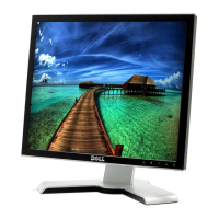
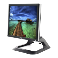
Dell 1707FPc
19
4. Input/Output Specification
4.1 Input Signal Connector
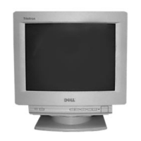
4.1.1 D-Sub Connector
Pin Signal Assignment Pin. Signal Assignment
1. Red Video 9. DDC +5V
2. Green Video 10. GND-Sync
3. Blue Video 11. GND
4. GND 12. DDC Data
5. Self Test 13. H-Sync
6. R-Ground 14. V-Sync
7. G-Ground 15. DDC Clock
8. B-Ground
VGA Connector layout
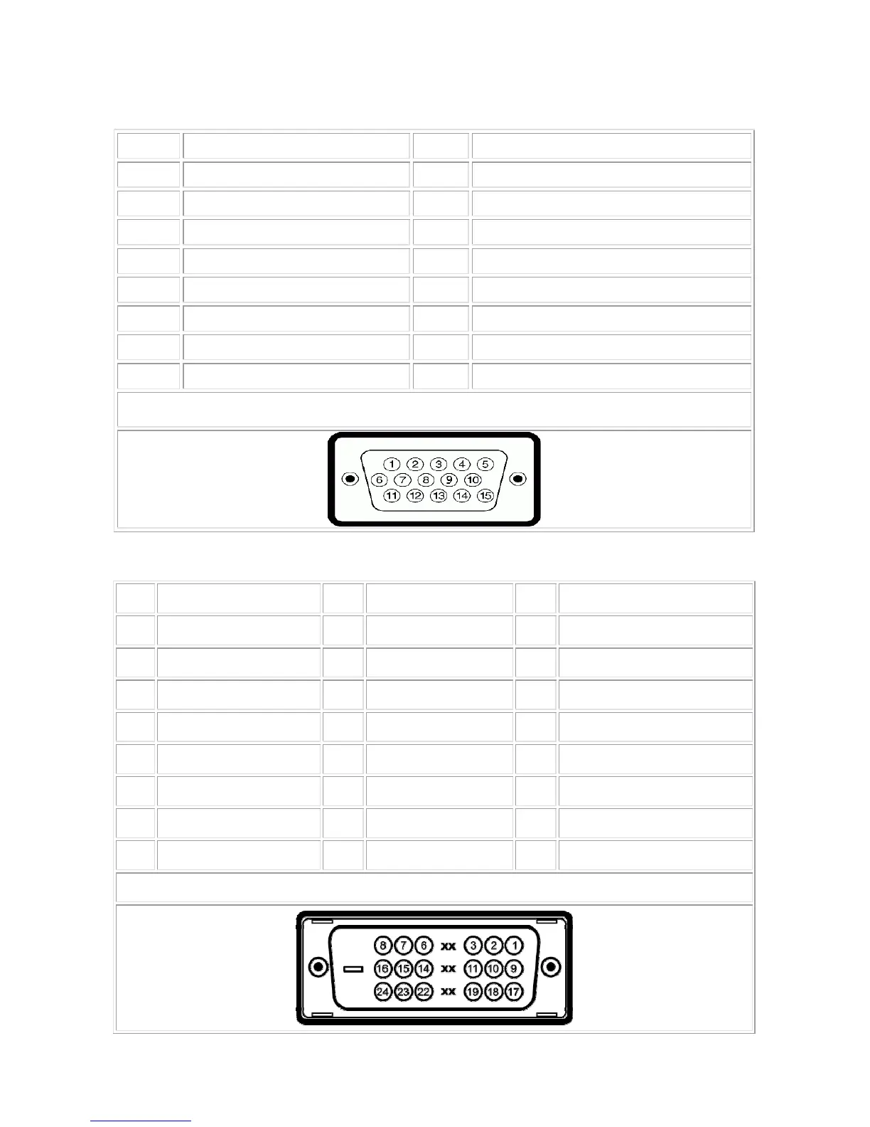
4.1.2 DVI Connector
Pin Signal Assignment Pin Signal Assignment Pin Signal Assignment
1 T.M.D.S. Data 2- 9 T.M.D.S. Data 1- 17 T.M.D.S. Data 0-
2 T.M.D.S. Data 2+ 10 T.M.D.S. Data 1+ 18 T.M.D.S. Data 0+
3 T.M.D.S. Data 2 Shield 11 T.M.D.S. Data 1 Shield 19 T.M.D.S. Data 0 Shield
4 No Pin 12 No Pin 20 No Pin
5 No Pin 13 No Pin 21 No Pin
6 DDC Clock 14 +5V Power 22 T.M.D.S. Clock Shield
7 DDC Data 15 Ground (for +5V) 23 T.M.D.S. Clock +
8 No Connect 16 Hot Plug Detect 24 T.M.D.S. Clock -
DVI Connector Layout