036
036
/
CHAPTER 5: INSTALLING ADDITIONAL OR REPLACEMENT COMPONENTS
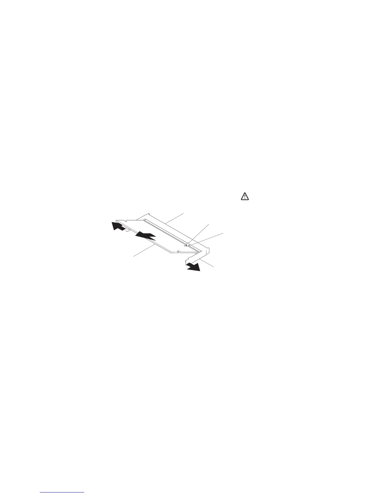
Use your ngertips to carefully spread apart the upper memory module 4.
connector’s spring-locks until the module pops up.
Remove the upper memory module.5.
Use your ngertips to carefully spread apart the lower memory module 6.
connector’s spring-locks until the module pops up.
Remove the lower memory module.7.
1
2
4
3
5
1 memory module connector 4 spring locks (2)
2 tab 5 memory module
3 notch
To replace the memory modules, perform the removal steps in reverse order. While
inserting the memory module into the connector align the notch on the memory
module to the tab on the connector.
NOTE: If the memory module is not installed properly, the computer may
not boot.