PS4000 Hardware Maintenance Basic Array Information
1–2
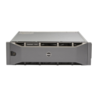
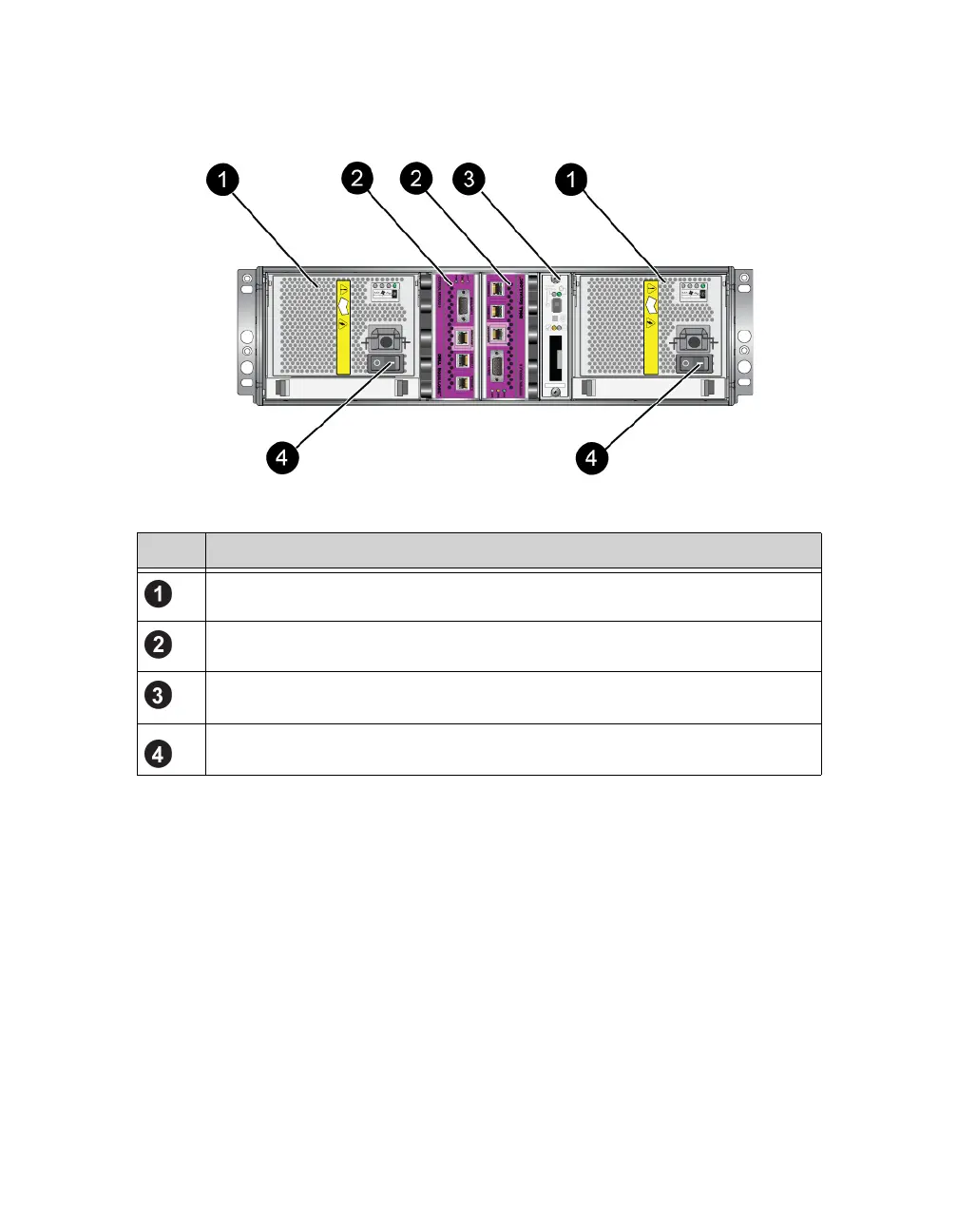
Figure 1-3: PS4000 Back Panel
Interpreting Operations Panel LEDs
The operations panel monitors array hardware components. The panel is not
redundant, but an array can continue to operate if it fails. See your array support
provider for information about servicing the operations panel.
Figure 1-4 shows the operations panel LEDs, which can alert you to errors and
conditions that require your attention. Table 1-2 describes the LEDs. Report any
serious problems to your array support provider.
Note: The serial number for your array is on a label on the operations panel.
Table 1-1: Back Panel Detail Description
Item Description
Power supply and cooling modules. The module on the right is 0, and the
module on the left is 1.
Control modules. The module on the right is 0, and the module on the left is 1.
Operation panel LED. Includes LEDs that show the status of the array (error
and warning conditions), power status, and location.
Power switches on the power supply and cooling modules. Turns power on and
off to the array.