4–1
4 Maintaining Power Supply Modules
The array includes two hot-swappable, combination power supply and cooling
modules.
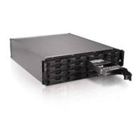
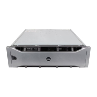
Interpreting the LEDs
Use the power supply and cooling module LEDs, shown in Figure 4-1 and
described in Table 4-1, to determine the module status and identify problems. The
power supply and cooling module LEDs show the power, fan, and array status.
Figure 4-1: Power Supply and Cooling Module LEDs
Identifying Failures
You can identify a power supply and cooling module failure by any or all of the
following:
• LEDs. See Interpreting the LEDs on page 4-1.
• Messages. A message on the console, in the event log, or in the Group
Manager GUI Alarms panel describes a power supply and cooling module
failure.
Table 4-1: Power Supply and Cooling Module LEDs
LED Color Description
Off Normal operation.
Orange DC power failure.
Off Normal operation.
Orange Fan failure.
Off Normal operation.
Orange AC power failure.
Off No power.
Green Normal operation.