212 | VLANs
www.dell.com | support.dell.com
Example of creating a VLAN and assigning interfaces
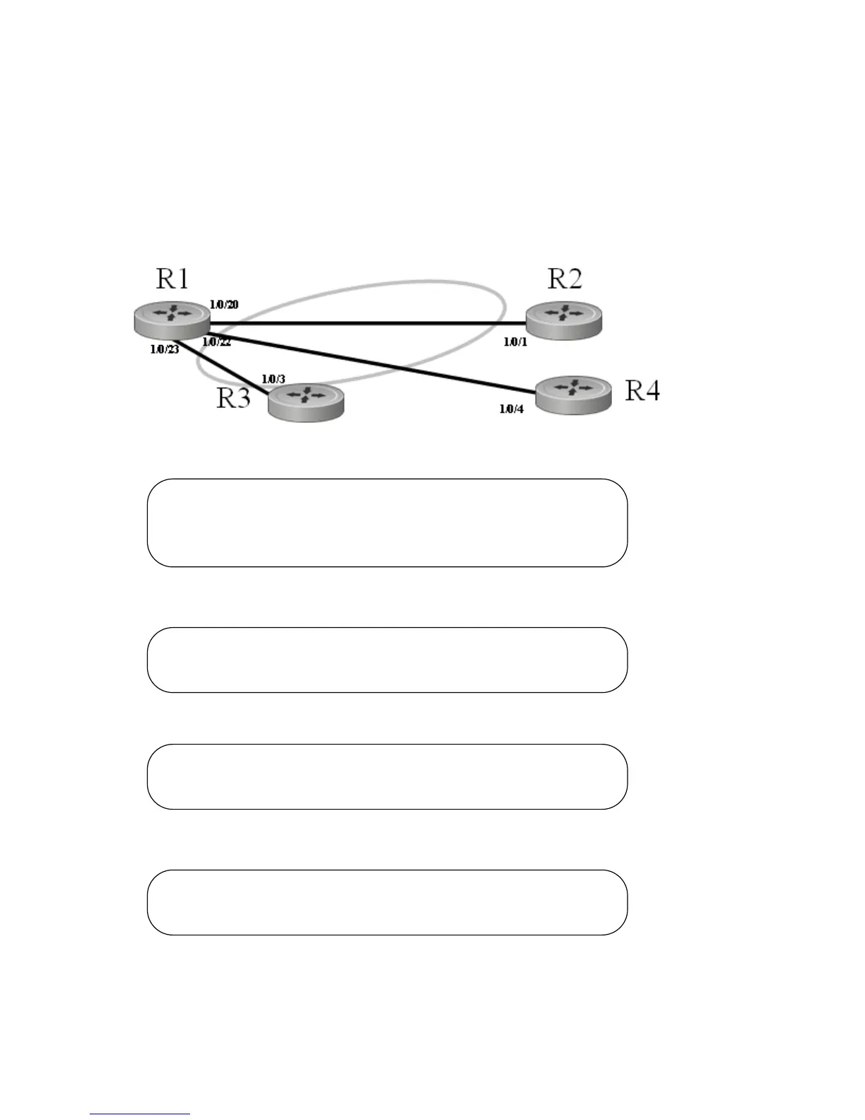
The diagram in this example shows four S-Series switches, R1, R2, R3, and R4, each configured with
VLAN 2 to handle traffic destined for R1.
This example creates VLAN 2 to connect four switches, with each switch having an interface that connects
through VLAN 2 to switch R1.
Figure 14-168. VLAN Topology
1. Create VLAN 2 on switch R1 and assign ports 20, 22, and 23:
2. Create VLAN 2 on switch R2 and assign port 1:
3. Create VLAN 2 on switch R3 and assign port 3:
4. Create VLAN 2 on switch R4 and assign port 4:
5. Optionally, after creating the VLAN, you can name it using the
name command. For example, if R1 in
this example is providing access to the Internet, you might name the VLAN “Internet_through_R1” on
each participating switch.
VLAN 2
R1 #config
R1 (Config)#interface vlan 2
R1 (Conf-if-vl-2)#untagged 1/0/20
R1 (Conf-if-vl-2)#untagged 1/0/22
R1 (Conf-if-vl-2)#untagged 1/0/23
R5 #config
R5 (Config)#interface vlan 2
R5 (Conf-if-vl-2)#untagged 1/0/1
R3 #config
R3 (Config)#interface vlan 2
R3 (Conf-if-vl-2)#tagged 1/0/3
R4 #config
R4 (Config)#interface vlan 2
R4 (Conf-if-vl-2)#untagged 1/0/4

 Loading...


