Installing the S25P System 15
Power
The S25P comes standard with two AC power supplies acting in load-sharing mode; see Figure 2 on
page 9. Use the power cords shipped with the S25P to connect it to AC power outlets, ideally on separate
circuits. Several versions of the power cord are available, based on country requirements.
S25P-DC
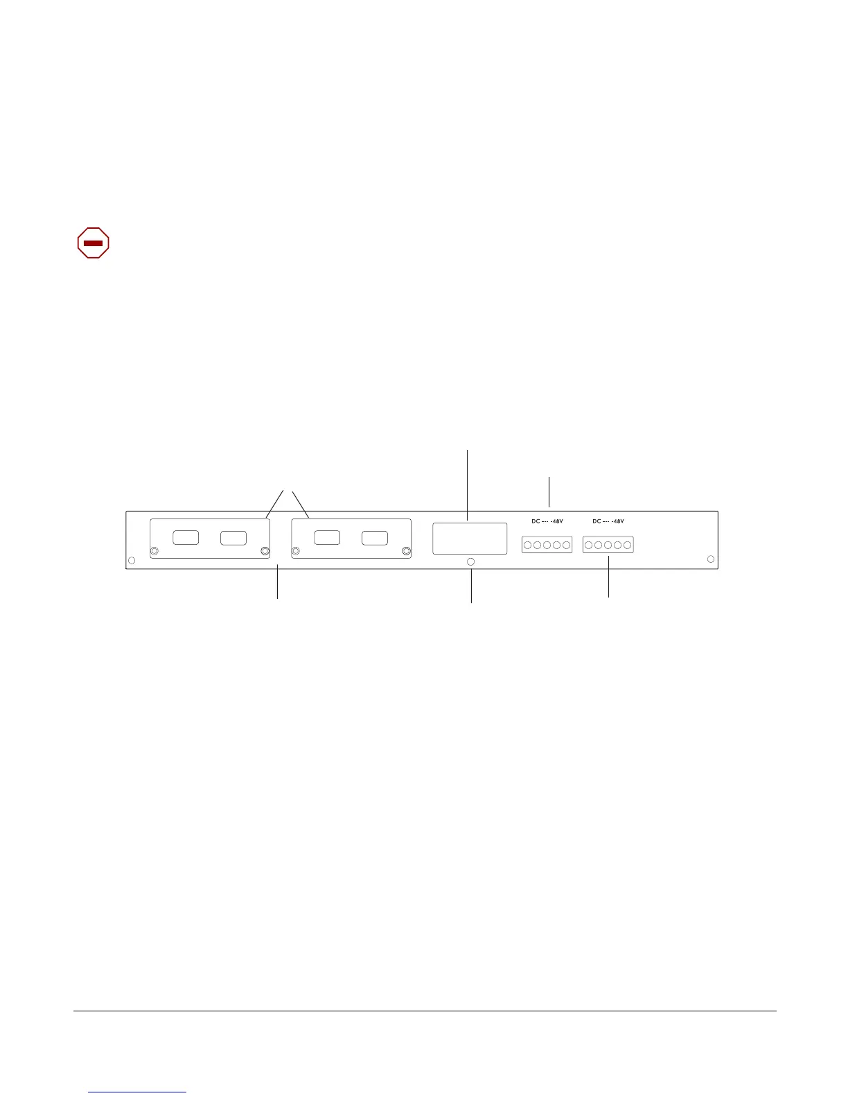
As shown below, the right side (as you face the back of the unit) of the S25P-DC contains two terminal
blocks for two DC power supply inputs acting in load-sharing mode. The left terminal block, as you face
the back, corresponds to the DC2 status LED on the front left of the switch; DC1 is on the right.
Figure 3 The S50N-DC Rear View
Figure 4 The S50N-DC Rear View
For details on connecting to a power source, see Supplying Power on page 27.
Storing Components
If you do not install your system and components immediately, Force10 Networks recommends that you
properly store the S25P and all optional components until you are ready to install them. Follow these
storage guidelines:
• Storage temperature should remain constant, in the range from -40° to 158° F (-40°C to 70° C).
• Storage humidity should be within 10 to 90% (relative humidity), non-condensing
• Store on a dry surface or floor, away from direct sunlight, heat, and air conditioning ducts.
• Store in a dust-free environment.
Caution: The power supply cord is used as the main disconnect device; ensure that the socket-outlet is
located/installed near the equipment and is easily accessible.
fn00158s25P-DC
10-Gigabit Modules or Stacking Modules (optional).
Optical ports numbered from left to right.
DC2
Ground Connector
DC1
Label (Part #, Serial #, MAC Address, Bar Code, FRU #)
Ethernet Port Numbers
25 to 28, Right to Left
FG
-48V
RTN
-48V
FG
-48V
RTN
-48V

 Loading...


