EasyManua.ls Logo

Dell Inspiron N4010 User Manual

Dell Inspiron N4010
53 pages
To Next Page IconTo Next Page
Page #1 background imageLoading...
Page #1 background image
Great user manuals database on UserManuals.info
Dell™Inspiron™N4010ServiceManual
Notes, Cautions, and Warnings
Information in this document is subject to change without notice.
©2010DellInc.Allrightsreserved.
Reproduction of these materials in any manner whatsoever without the written permission of Dell Inc. is strictly forbidden.
Trademarks used in this text: Dell, the DELL logo, and Inspiron are trademarks of Dell Inc.; Bluetooth is a registered trademark owned by Bluetooth SIG, Inc. and is used by Dell
under license; Microsoft, Windows, Windows Vista, and the Windows Vista start button logo are either trademarks or registered trademarks of Microsoft Corporation in the United
States and/or other countries.
Other trademarks and trade names may be used in this document to refer to either the entities claiming the marks and names or their products. Dell Inc. disclaims any
proprietary interest in trademarks and trade names other than its own.
RegulatorymodelP11GseriesRegulatorytypeP11G001
March2010Rev.A00
Before You Begin
Battery
Module Cover
Memory Module(s)
Optical Drive
Keyboard
Palm Rest
Power Button Board
Coin-Cell Battery
Wireless Mini-Card(s)
Internal Card With Bluetooth®Wireless Technology
Thermal Fan
System Board
Hard Drive
Thermal Cooling Assembly
Processor Module
Speakers
Display
Camera Module
Middle Cover
I/O Board
Daughter Board
AC Adapter Connector
Flashing the BIOS
NOTE: A NOTE indicates important information that helps you make better use of your computer.
CAUTION: A CAUTION indicates either potential damage to hardware or loss of data and tells you how to avoid the problem.
WARNING: A WARNING indicates a potential for property damage, personal injury, or death.
Question and Answer IconNeed help?

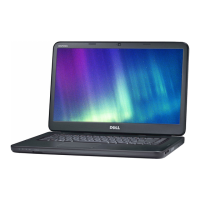
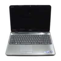
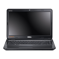
Do you have a question about the Dell Inspiron N4010 and is the answer not in the manual?

Dell Inspiron N4010 Specifications

General IconGeneral
ProcessorIntel Core i3/i5
RAMUp to 8GB DDR3
StorageUp to 500GB HDD
Operating SystemWindows 7 Home Premium
Battery6-cell Lithium Ion
Optical DriveDVD+/-RW
Wireless802.11b/g/n
Webcam1.3 MP
Display14.0 inch HD (1366 x 768)
GraphicsIntel HD Graphics
WeightApprox. 2.2 kg (4.85 lbs)
Ports3 x USB 2.0, HDMI, VGA, Ethernet

Summary

Notes, Cautions, and Warnings

AC Adapter Connector

Removing the AC Adapter Connector

Procedure to remove the AC adapter connector from the computer base.

Replacing the AC Adapter Connector

Procedure to install the AC adapter connector onto the computer base.

Module Cover

Removing the Module Cover

Procedure to remove the computer's module cover.

Replacing the Module Cover

Procedure to install the computer's module cover.

Before You Begin

Recommended Tools

Lists tools required for component removal and installation procedures.

Turning Off Your Computer

Steps to safely shut down the computer before servicing.

Before Working Inside Your Computer

Safety guidelines to follow before performing internal computer work.

Flashing the BIOS

Internal Card With Bluetooth® Wireless Technology

Removing the Bluetooth Card

Procedure to remove the Bluetooth card from the computer.

Replacing the Bluetooth Card

Procedure to install the Bluetooth card into the computer.

Camera Module

Removing the Camera Module

Procedure to remove the camera module from the display cover.

Replacing the Camera Module

Procedure to install the camera module onto the display cover.

Coin-Cell Battery

Removing the Coin-Cell Battery

Procedure to remove the coin-cell battery from the system board slot.

Replacing the Coin-Cell Battery

Procedure to install the coin-cell battery into the system board slot.

Processor Module

Removing the Processor Module

Procedure to remove the processor module from the ZIF socket.

Replacing the Processor Module

Procedure to install the processor module into the ZIF socket.

Thermal Cooling Assembly

Removing the Thermal Cooling Assembly

Procedure to remove the thermal cooling assembly from the system board.

Replacing the Thermal Cooling Assembly

Procedure to install the thermal cooling assembly onto the system board.

Daughter Board

Removing the Daughter Board

Procedure to remove the daughter board from the computer base.

Replacing the Daughter Board

Procedure to install the daughter board onto the computer base.

Display Assembly

Removing the Display Assembly

Procedure to remove the display assembly from the computer base.

Replacing the Display Assembly

Procedure to install the display assembly onto the computer base.

Display Bezel

Removing the Display Bezel

Procedure to remove the display bezel from the display panel.

Replacing the Display Bezel

Procedure to install the display bezel onto the display panel.

Display Panel

Removing the Display Panel

Procedure to remove the display panel from the display cover.

Replacing the Display Panel

Procedure to install the display panel onto the display cover.

Display Hinges

Removing the Display Hinges

Procedure to remove the display hinges from the display cover.

Replacing the Display Hinges

Procedure to install the display hinges onto the display cover.

Hinge Caps

Removing the Hinge Caps

Procedure to remove the hinge caps from the display hinges.

Replacing the Hinge Caps

Procedure to install the hinge caps onto the display hinges.

Thermal Fan

Removing the Thermal Fan

Procedure to remove the thermal fan from the computer base.

Replacing the Thermal Fan

Procedure to install the thermal fan onto the computer base.

Hard Drive

Removing the Hard Drive

Procedure to remove the hard-drive assembly from the system board.

Replacing the Hard Drive

Procedure to install the hard-drive assembly onto the system board.

Middle Cover

Removing the Middle Cover

Procedure to remove the middle cover from the computer base.

Replacing the Middle Cover

Procedure to install the middle cover onto the computer base.

I/O Board

Removing the I/O Board

Procedure to remove the I/O board from the computer base.

Replacing the I/O Board

Procedure to install the I/O board onto the computer base.

Keyboard

Removing the Keyboard

Procedure to remove the keyboard from the palm rest.

Replacing the Keyboard

Procedure to install the keyboard onto the palm rest.

Memory Module(s)

Removing the Memory Module(s)

Procedure to remove memory modules from SO-DIMM sockets.

Replacing the Memory Module(s)

Procedure to install memory modules into SO-DIMM sockets.

Wireless Mini-Card(s)

Removing the Mini-Card(s)

Procedure to remove wireless Mini-Cards from daughter board connectors.

Replacing the Mini-Card(s)

Procedure to install wireless Mini-Cards into daughter board connectors.

Optical Drive

Removing the Optical Drive

Procedure to remove the optical-drive assembly from its compartment.

Replacing the Optical Drive

Procedure to install the optical-drive assembly into its compartment.

Palm Rest

Removing the Palm Rest

Procedure to remove the palm rest from the computer base.

Replacing the Palm Rest

Procedure to install the palm rest onto the computer base.

Power Button Board

Removing the Power Button Board

Procedure to remove the power button board from the palm rest.

Replacing the Power Button Board

Procedure to install the power button board onto the palm rest.

Battery

Removing the Battery

Procedure to remove the main battery from the battery bay.

Replacing the Battery

Procedure to install the main battery into the battery bay.

Speakers

Removing the Speakers

Procedure to remove the speakers from the computer base.

Replacing the Speakers

Procedure to install the speakers onto the computer base.

System Board

Removing the System Board

Procedure to remove the system board assembly from the computer base.

Replacing the System Board

Procedure to install the system board assembly onto the computer base.

Entering the Service Tag in the BIOS

Steps to enter the service tag in the BIOS after system board replacement.

Related product manuals