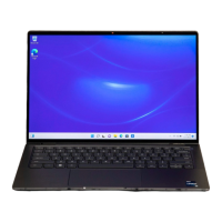
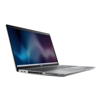
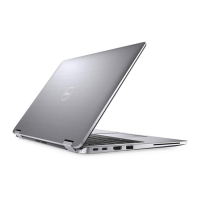
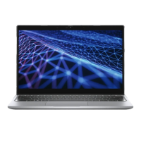
Figure 46. Removing the display assembly
Steps
1. Disconnect the battery cable from the battery cable connector on the system board.
2. Remove the two (M1.6x3) screws that secure the display cable/Type-C bracket in place.
3. Lift the display cable/Type-C bracket off the system board.
4. Disconnect the camera cable and display cable from the connector (CAMERA) on the system board.
NOTE:
The connector for the display cable uses a latch that locks it in place on the system board which technicians
must flip open to disconnect the display cable from the system board. After flipping open the latch, technicians must
grasp the left and right sides of the cable's connector head and disconnect the display cable from the system board in a
direct upward motion to prevent damage to the connector's pins.
CAUTION: Do not attempt to disconnect the display cable from the connector on the system board without
flipping open the latch first.
66 Removing and installing Field Replaceable Units (FRUs)

 Loading...


