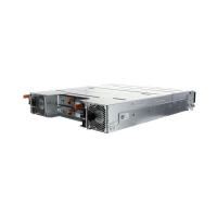
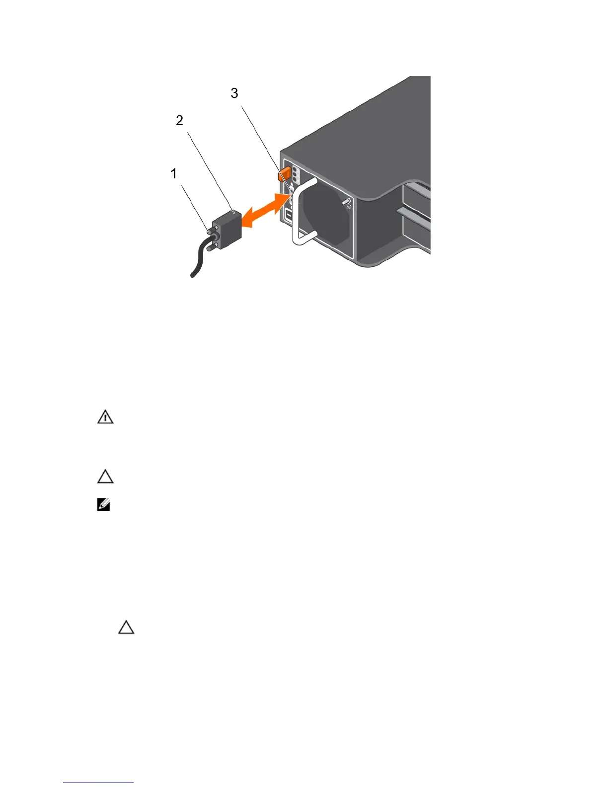
Figure 19. Connecting the dc power cables
1. attached (trapped) finger screws 2. connector on the power supply cable
3. connector on the power supply module
Removing a DC power supply
WARNING: For equipment using –(48–60) V DC power supplies, a qualified electrician must
perform all connections to DC power and to safety grounds. Do not attempt connecting to DC
power or installing grounds yourself .All electrical wiring must comply with applicable local or
national codes and practices. Damage due to servicing that is not authorized by Dell is not
covered by your warranty. Read and follow all safety instructions that came with the product.
CAUTION: The system requires one power supply for normal operation. On power-redundant
systems, remove and replace one power supply at a time when a system is turned on.
NOTE: You must unlatch and lift the optional cable management arm if it interferes with power
supply removal. For information about the cable management arm, see the system’s rack
documentation.
1. Turn off the power switches on the power supply module.
2. Remove the strap that secures the wires to the power supply module handle.
3. Disconnect the power wires from the power source and the connector from the power supply
module you intend to remove.
4. Disconnect the safety ground wire.
5. Press the release latch and slide the power supply module out of the chassis.
CAUTION: The power supply module is heavy; support it with both hands.
25