Steps
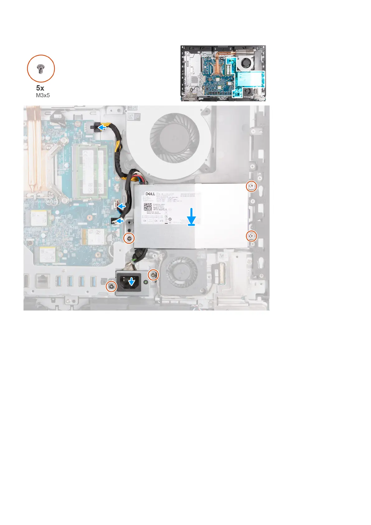
1. Place the power-supply unit and the power-supply unit connector on the display-assembly base.
2. Align the screw holes on the power-supply unit with the screw holes on the display-assembly base.
3. Replace the three screws (M3x5) that secure the power-supply unit to the display-assembly base.
4. Align the screw holes on the power-supply connecty bracket with the screw holes on the display-assembly base.
5. Replace the two screws (M3x5) that secure the power-supply connector bracket to the display-assembly base.
6. Connect the processor-power cable (ATX CPU) to the system board.
7. Connect the control-signal cable (CTRL) to the system board.
8. Connect the system-board power cable (ATX SYS) to the system board.
Next steps
1. Install the I/O cover.
2. Install the system-board shield.
3. Install the back cover.
4. Install the stand.
5. Follow the procedure in After working inside your computer.
Removing and installing Customer Replaceable Units (CRUs)
75
 Loading...