EasyManuals Logo

Dell OptiPlex All-in-One Plus 7410 User Manual

Dell OptiPlex All-in-One Plus 7410
123 pages
To Next Page IconTo Next Page
To Previous Page IconTo Previous Page
Page #98 background imageLoading...
Page #98 background image
Steps
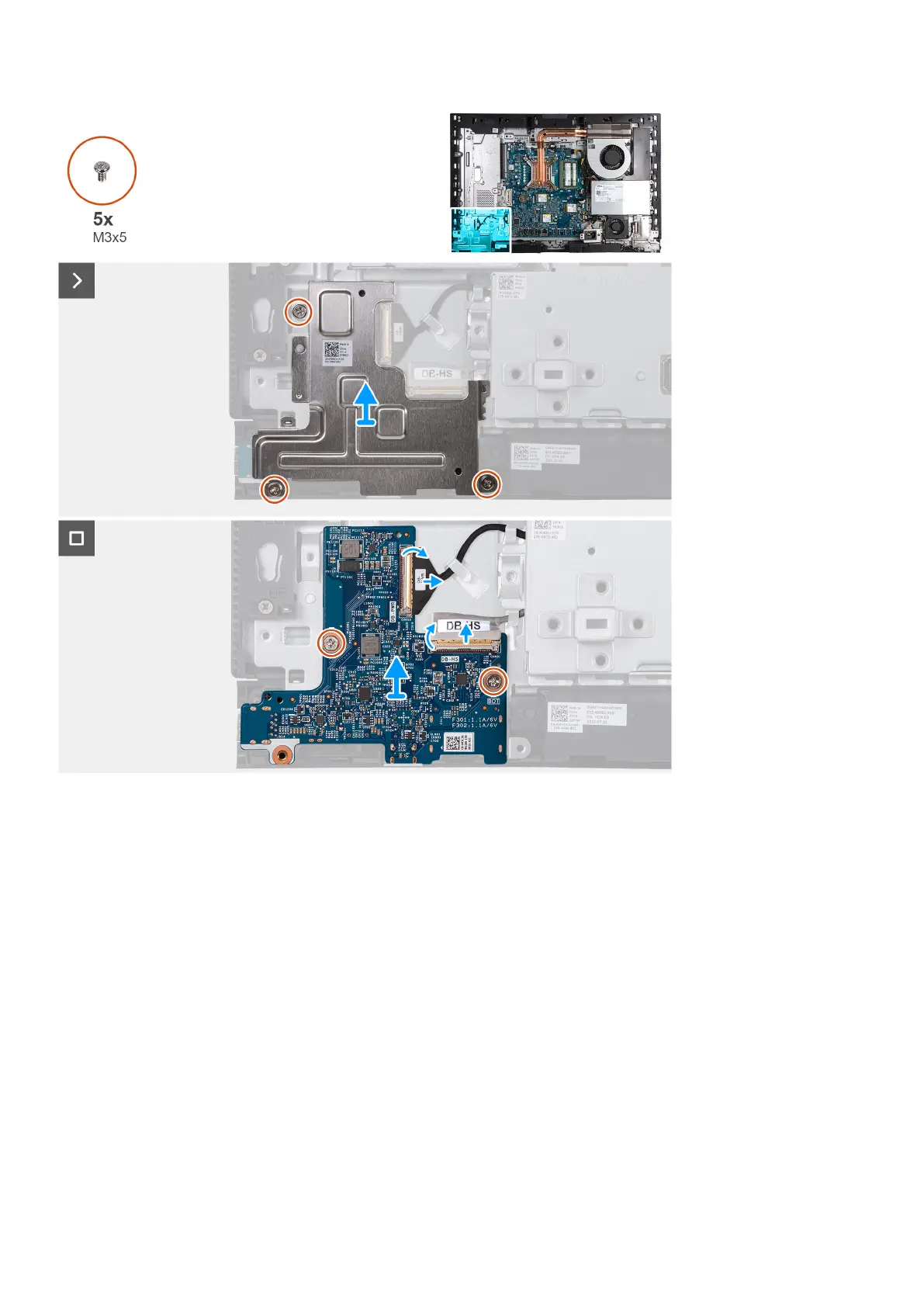
1. Remove the three screws (M3x5) that secure the power-button and I/O board shield to the display-assembly base.
2. Lift the power-button and I/O board shield off the display-assembly base.
3. Lift the latch and disconnect the power cable (DB-PWR) from the power-button and I/O board.
4. Lift the latch and disconnect the high-speed cable (DB-HS) from the power-button and I/O board.
5. Remove the two screws (M3x5) that secure the power-button and I/O board to the display-assembly base.
6. Lift the power-button and I/O board off the display-assembly base.
Installing the power-button and I/O board
Prerequisites
If you are replacing a component, remove the existing component before performing the installation process.
About this task
The following image(s) indicate the location of the power-button and I/O board and provides a visual representation of the
installation procedure.
98
Removing and installing Field Replaceable Units (FRUs)

Table of Contents

Other manuals for Dell OptiPlex All-in-One Plus 7410

Questions and Answers:

Question and Answer IconNeed help?

Do you have a question about the Dell OptiPlex All-in-One Plus 7410 and is the answer not in the manual?

Dell OptiPlex All-in-One Plus 7410 Specifications

General IconGeneral
Operating SystemWindows 11 Pro
WirelessWi-Fi 6E, Bluetooth 5.2
Processor13th Gen Intel Core i5/i7/i9
Display23.8-inch FHD (1920 x 1080) Anti-Glare
MemoryUp to 64GB
StorageUp to 2TB PCIe NVMe SSD
GraphicsIntel UHD Graphics
AudioStereo speakers with Waves MaxxAudio Pro
Webcam5MP
Ports (Front)USB-C, USB-A, headphone/microphone combo
Ports (Rear)HDMI
Power Supply90W External Adapter

Related product manuals