5. Free the system board from the back I/O panel by sliding it towards the right and lift the system board out of the chassis.
Installing the system board
Prerequisites
If you are replacing a component, remove the existing component before performing the installation procedure.
About this task
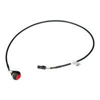
The following image indicates the connectors on your system board.
1. Intrusion-switch cable 2. Processor-power cable
3. Processor-fan cable 4. UDIMM slots
From the left (a>b):
DIMM 1
DIMM 2
5. Power-button cable 6. System-power cable
7. M.2 2230/2280 solid-state drive slot 8. M.2 WLAN slot
9. Hard-drive data cable (SATA 0) 10. Optical-drive/hard-drive data cable (SATA 1)
11. SATA power cable 12. Internal-speaker cable
13. PCIe x16 slot (SLOT 2) 14. PCIe x1 slot (SLOT 1)
15. Coin-cell battery socket 16. Processor socket
17. Video cable 18. I/O cable
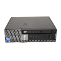
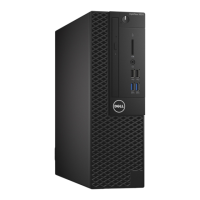
The following image indicates the location of the system board and provides a visual representation of the installation procedure.
98
Removing and installing Field Replaceable Units (FRUs)