Item Indicator, button, or
connector
Icon Description
NOTE: LCD panel is not available in a cabled hard drive
chassis.
7 USB management port/
iDRAC managed USB port
Functions as a regular USB port or provide access to the iDRAC
Direct features. For more information, see the iDRAC User’s Guide
at Dell.com/idracmanuals.
8 USB connector Enables you to connect USB devices to the system. The port is
USB 2.0-compliant.
9 Information tag Contains system information such as service tag, NIC, MAC
address for your reference. The information tag is a slide-out label
panel.
10 Hard drives slots Enables you to install up to four 3.5-inch hot-swappable hard
drives or four 2.5-inch hot-swappable hard drives in 3.5-inch hard
drive adapters.
11 Optical drive slot Enables you to install an optional slim SATA DVD-ROM drive or
DVD+/-RW drive.
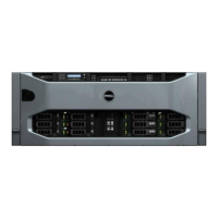
Figure 3. Front panel features and indicators — eight 2.5-inch hot-swappable hard drives or SSDs chassis
Table 2. Front panel features and indicators—eight 2.5-inch hot-swappable hard drives or SSDs chassis
Item Indicator, Button, or
Connector
Icon Description
1 Power-on indicator, power
button
Enables you to know the power status of the system. The
power-on indicator glows when the system power is on. The
power button controls the power supply output to the system.
NOTE: On ACPI-compliant operating systems, turning
o the system by pressing the power button causes the
system to perform a graceful shutdown before power to
the system is turned o.
2 NMI button
Enables you to troubleshoot software and device driver errors
when running certain operating systems. This button can be
pressed by using the end of a paper clip.
Use this button only if directed to do so by qualied support
personnel or by the operating system's documentation.
3 System identication button Enables you to locate a particular system within a rack. The
identication buttons are on the front and back panels. When
one of these buttons is pressed, the LCD panel on the front and
12

 Loading...

