Dell
PowerEdge R815 Technical Guide vi
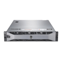
Figure 3. Front Panel View (with Bezel) ..................................................................... 14
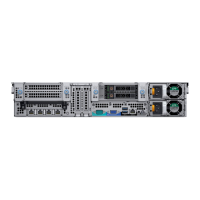
Figure 4. Back Panel View ..................................................................................... 14
Figure 5. Side View ............................................................................................. 15
Figure 6. Internal Chassis View ............................................................................... 16
Figure 7. Cabling Diagram ..................................................................................... 18
Figure 8. LCD Panel ............................................................................................ 19
Figure 9. USB Port .............................................................................................. 20
Figure 10. R815 ReadyRails Sliding Rails with Optional CMA ............................................ 43
Figure 11. 2U Threaded Rack Adapter Brackets Kit ...................................................... 44
Figure 12. R815 Mounted in the B2 Sliding Rails .......................................................... 45
Figure 13. R815 CMA Mounted on the Side Opposite the Power Supplies (Recommended)......... 46
 Loading...