Installing System Components 63
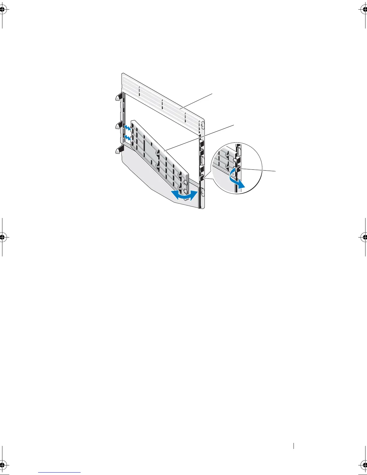
Figure 3-4. Removing and Installing the Front Bezel Insert
Installing Front Bezel Insert
1
To replace the insert on the front bezel, from the back of the bezel, fit the
tabs on the end of the insert into the notches on the bezel.
2
Snap the other end of the insert into place. See Figure 3-4.
EMI Filler Panel
Depending on the configuration of your system, an electromagnetic
interference (EMI) filler panel may be installed in one or more of the 5.25-
inch optical drive bays at the front of the system. EMI filler panels are
essential for airflow efficiency and for electromagnetic interference
protection. Before installing an optical drive, the corresponding EMI filler
panel must first be removed.
Removing an EMI Filler Panel
1
Turn off the system and attached peripherals, and disconnect the system
from the electrical outlet.
2
Open the system. See "Opening the System" on page 59.
1 front bezel 2 front bezel insert
3 insert tab
Coaster_HOM.book Page 63 Monday, November 3, 2014 3:23 PM

 Loading...