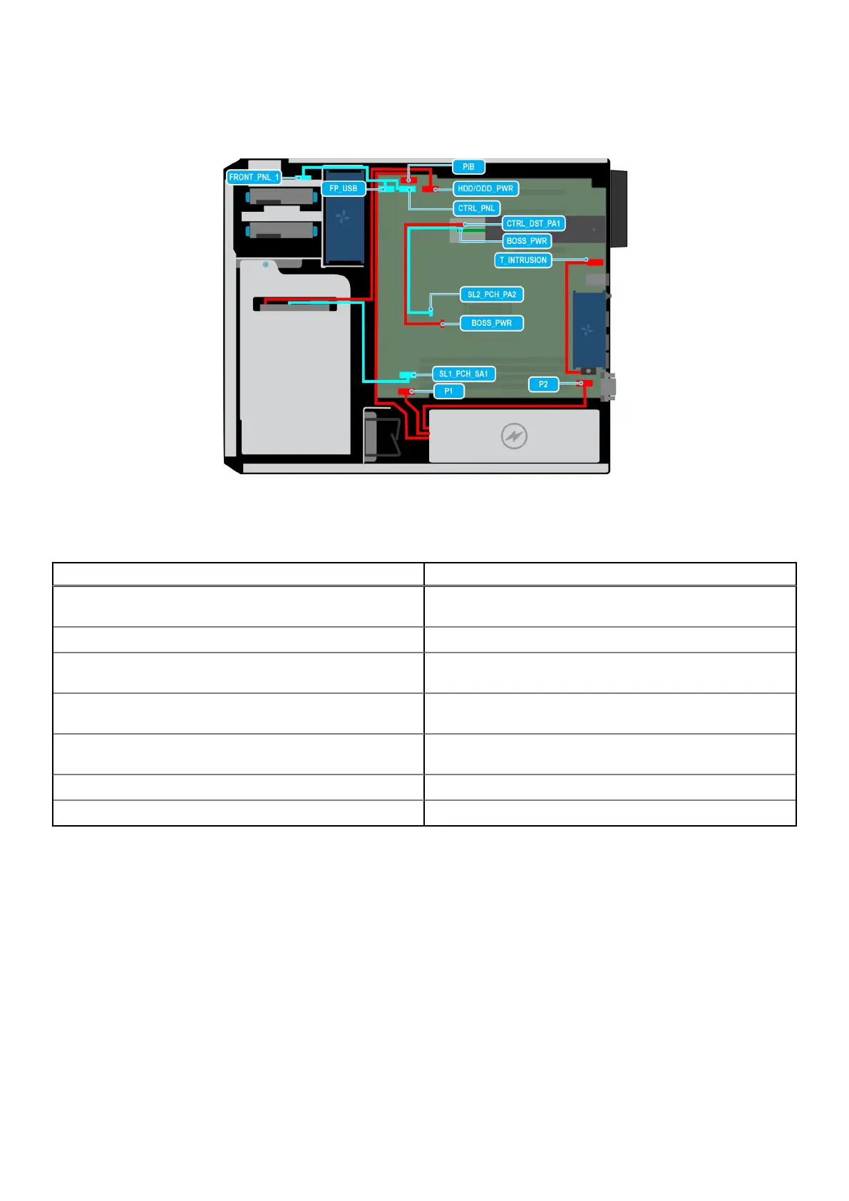
Cable routing
Figure 30. Cable routing - 3 x 3.5 inch Chip SATA
Table 57.
Connector descriptions for a 3 x 3.5 inch Chip SATA
From To
MB_FP_USB (front USB connector on system board) and
CTRL_PNL (control panel connector on system board)
FIO (control panel connector)
MB_T_INTRUSION (INTRUSION connector on system board) INTRUSION
MB_SL1_PCH_SA1 (signal connector on system board) HDD0, HDD1, HDD2 (signal connector connecting through the
drives 0, 1, 2)
MB_PIB (power interposer board connector on system board)
and MB_P1 (system power connector on system board)
PSU (Power supply unit)
MB_HDD/ODD_PWR (Drives/Optical disc drive power
connector on the system board)
HDD0, HDD1, HDD2 (connecting through the drives 0, 1, 2)
MB_SL2_PCH_PA2 (signal connector on the system board) BOSS_CTRL_DST_PA1 (BOSS input connector)
MB_BOSS_PWR (power connector on system board) BOSS_PWR (BOSS module power connector)
Disassembly and reassembly 65









 To Next Page