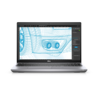
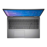
Steps
1. Place the display assembly on the system, and align the screw holes on the display hinges with screw holes on the system
board.
2. Replace the six screws (M2.5x5) that secure the display hinges to the system board.
3. Close the display.
4. Connect the sensor-board cable to the connector on the system board and adhere the tape to secure the cable to the
system board.
5. Route the display and eDP cable through the routing guide on the system board.
6. Connect the eDP cable to the connector on the system board.
7. Connect the display cable to the connector on the system board.
8. Adhere the tape that secures the display cable to the system board.
9. Align the screw holes on the eDP cable bracket with the screw holes on the system board.
10. Replace the two screws (M2x3) that secure the eDP cable bracket to the system board.
Removing and installing components
69
 Loading...


