Chapter 4 Display and Operation
Revision January 2011 4-5
P0-02
Setting
Display Message Description Unit
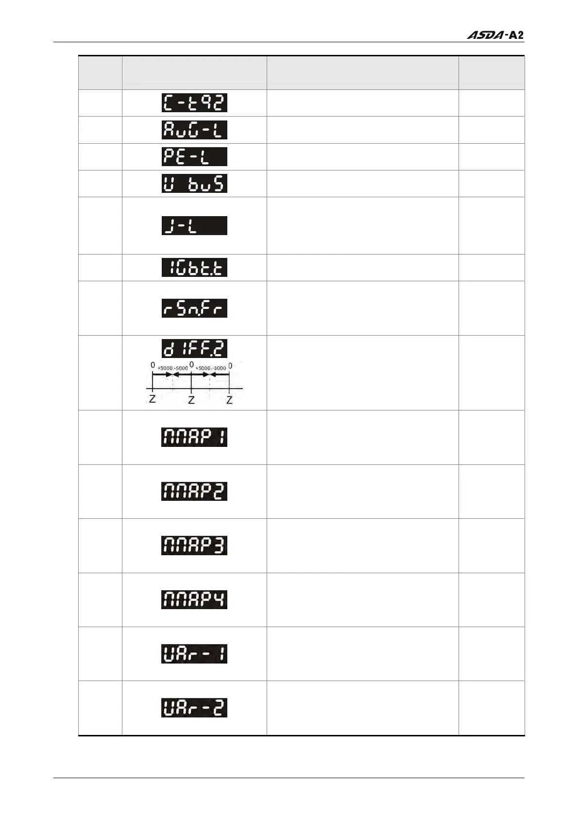
11
Torque input command [%]
12
Average load [%]
13
Peak load
[%]
14
Main circuit voltage [Volt]
15
Ratio of load inertia to Motor inertia
(Please note that if the display is
130, it indicates that the actual
inertia is 13.0)
[0.1times]
16
IGBT temperature
[
o
C]
17
Resonance frequency (The low byte
is the first resonance point and the
high byte is the second resonance
point.)
[Hz]
18
Absolute pulse number relative to
encoder (use Z phase as home). The
value of Z phase home point is 0,
and it can be the value from -5000
to +5000 pulses.
-
19
Mapping Parameter 1: Display the
content of parameter P0-25
(mapping target is specified by
parameter P0-35)
-
20
Mapping Parameter 2: Display the
content of parameter P0-26
(mapping target is specified by
parameter P0-36)
-
21
Mapping Parameter 3: Display the
content of parameter P0-27
(mapping target is specified by
parameter P0-37)
-
22
Mapping Parameter 4: Display the
content of parameter P0-28
(mapping target is specified by
parameter P0-38)
-
23
Status Monitor 1: Display the
content of parameter P0-09 (the
monitor status is specified by
parameter P0-17)
-
24
Status Monitor 2: Display the
content of parameter P0-10 (the
monitor status is specified by
parameter P0-18)
-
Call 1(800)985-6929 for Sales
Call 1(800)985-6929 for Sales