Chapter 3 Connections and Wiring
3-30 Revision January 2011
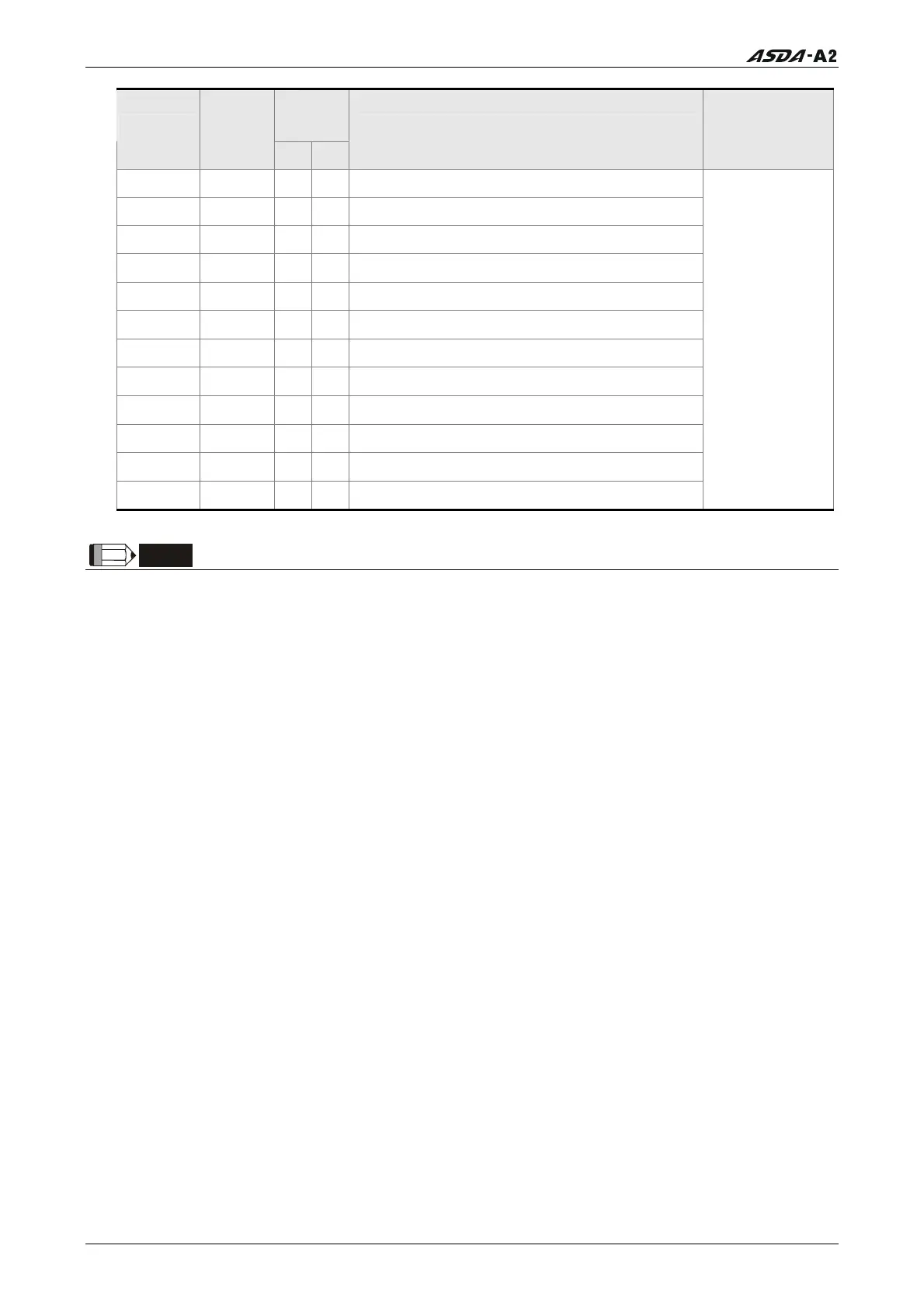
Pin No.
(Default)
DO Signal
Assi
ned
Control
Mode
+ -
Details
Wiring Diagram
(Refer to 3.3.4)
SDO_4 ALL - - Output the status of bit04 of P4-06.
SDO_5 ALL - - Output the status of bit05 of P4-06.
SDO_6 ALL - - Output the status of bit06 of P4-06.
SDO_7 ALL - - Output the status of bit07 of P4-06.
SDO_8 ALL - - Output the status of bit08 of P4-06.
SDO_9 ALL - - Output the status of bit09 of P4-06.
SDO_A ALL - - Output the status of bit10 of P4-06.
SDO_B ALL - - Output the status of bit11 of P4-06.
SDO_C ALL - - Output the status of bit12 of P4-06.
SDO_D ALL - - Output the status of bit13 of P4-06.
SDO_E ALL - - Output the status of bit14 of P4-06.
SDO_F ALL - - Output the status of bit15 of P4-06.
C5/C6/C7/C8
NOTE
1)
PINS 3 & 2 can either be TSPD or HOME dependent upon control mode selected.
2)
The DO signals that do not have pin numbers in Tables 3.B are not default DO signals. If
the users want to use these non-default DO signals, the users need to change the settings
of parameters P2-18 ~ P2-22. The “state” of the output function may be turned ON or OFF
as it will be dependant on the settings of parameters P2-18 ~ P2-22. Please refer to section
3.3.3 for details.
Call 1(800)985-6929 for Sales
Call 1(800)985-6929 for Sales