Chapter 3 Connections and Wiring
Revision January 2011 3-33
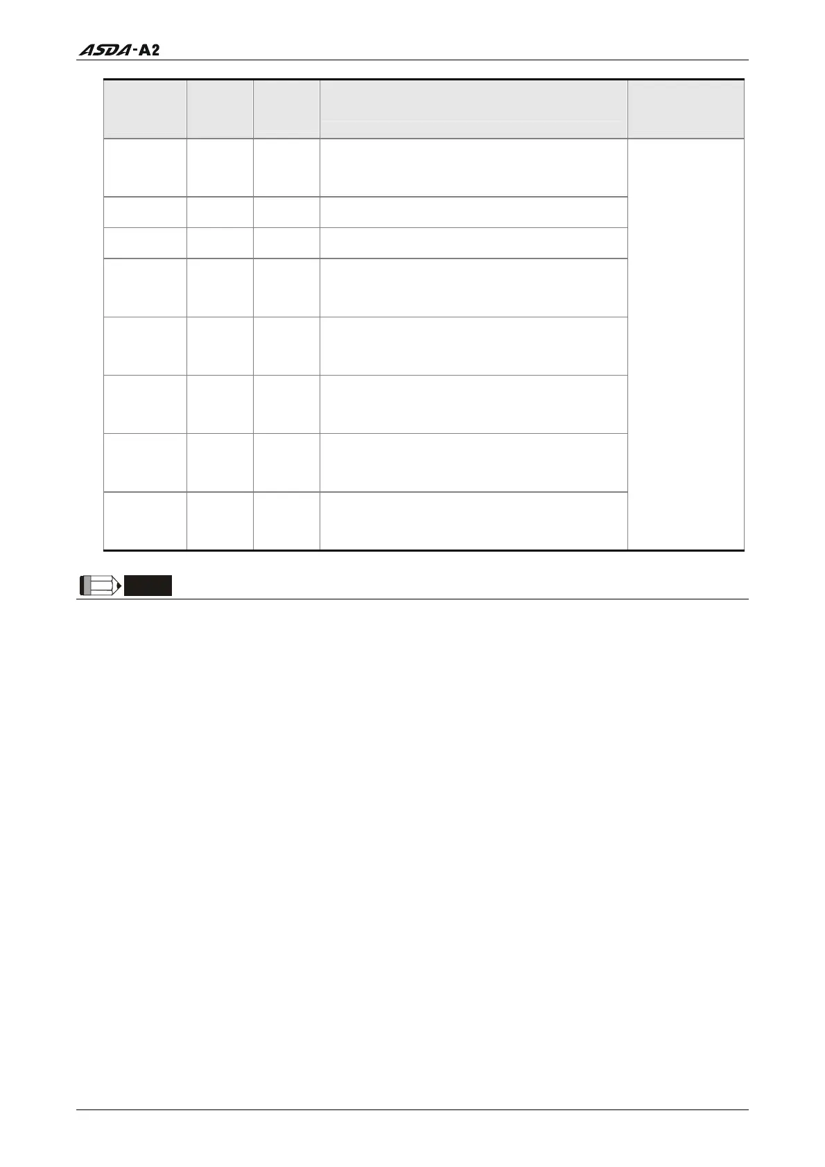
DI
Signal
Assi
ned
Control
Mode
Pin No.
(Default)
Details
Wiring Diagram
(Refer to 3.3.4)
JOGD ALL -
Reverse JOG input. When JOGD is activated,
the motor will JOG in reverse direction. [see
P4-05]
EV1 PR - Event trigger command 1.
EV2 PR - Event trigger command 2.
EV3 PR -
Event trigger command 3. (available for
ASDA-A2 firmware version V1.008 sub04 or
later)
EV4 PR -
Event trigger command 4. (available for
ASDA-A2 firmware version V1.008 sub04 or
later)
GNUM0
PT, PR,
PT-S, PR-
S
-
Electronic gear ratio (Numerator) selection 0.
[See P2-60~P2-62]
GNUM1
PT, PR,
PT-S, PR-
S
-
Electronic gear ratio (Numerator) selection 1.
[See P2-60~P2-62]
INHP PT, PT-S
-
Pulse inhibit input. When the drive is in
position mode, if INHP is activated, the
external pulse input command is not valid.
C9/C10/C11
/C12
NOTE
1)
The DI signals that do not have pin numbers in Tables 3.C are not default DI signals. If the
users want to use these non-default DI signals, the users need to change the settings of
parameters P2-10 ~ P2-17. The “state” of the output function may be turned ON or OFF as it
will be dependant on the settings of parameters P2-10 ~ P2-17. Please refer to section
3.3.3 for details.
Call 1(800)985-6929 for Sales
Call 1(800)985-6929 for Sales