Chapter 3 Connections and Wiring
3-34 Revision January 2011
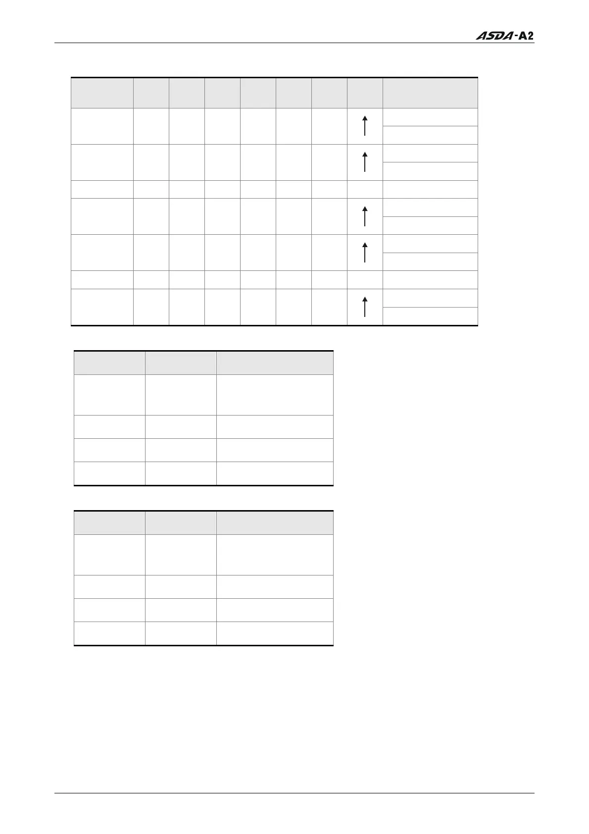
Table 3.D Source of Position Command
Position
Command
POS5 POS4 POS3 POS2
POS1
POS0
CTRG
Parameters
P6-00
P1 ON ON ON ON ON ON
P6-01
P6-02
P2 ON ON ON ON ON OFF
P6-03
~ ~
P6-98
P50 OFF OFF ON ON OFF
ON
P6-99
P7-00
P51 OFF OFF ON ON OFF
OFF
P7-01
~ ~
P7-26
P64 OFF OFF OFF OFF
OFF
OFF
P7-27
Table 3.E Source of Speed Command
SPD1 SPD0 Parameters
OFF OFF
S mode: analog input
Sz mode: 0
OFF ON P1-09
ON OFF P1-10
ON ON P1-11
Table 3.F Source of Torque Command
TCM1 TCM0 Parameters
OFF OFF
T mode: analog input
Tz mode: 0
OFF ON P1-12
ON OFF P1-13
ON ON P1-14
The default DI and DO signals in different control mode are listed in the following table
3.G and table 3.H. Although the content of the table 3.G and table 3.H do not provide
more information than the table 3.B and table 3.C above, as each control mode is
separated and listed in different row, it is easy for user to view and can avoid confusion.
However, the Pin number of each signal can not be displayed in the table 3.G and table
3.H.
Call 1(800)985-6929 for Sales
Call 1(800)985-6929 for Sales