Chapter 3 Connections and Wiring
Revision January 2011 3-39
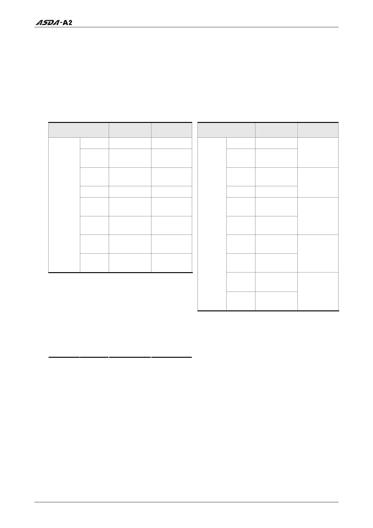
3.4.3 User-defined DI and DO signals
If the default DI and DO signals could not be able to fulfill users’ requirements, there are
still user-defined DI and DO signals. The setting method is easy and they are all defined
via parameters. The user-defined DI and DO signals are defined via parameters P2-10 to
P2-17 and P2-18 to P2-22.
Please refer to the following Table 3.I for the settings.
Table 3.I User-defined DI and DO signals
Signal Name Pin No. Parameters
Signal Name Pin No. Parameters
DI1- Pin 9 of CN1 P2-10
DO1+
Pin 7 of CN1
DI2-
Pin 10 of
CN1
P2-11
DO1- Pin 6 of CN1
P2-18
DI3-
Pin 34 of
CN1
P2-12
DO2+
Pin 5 of CN1
DI4- Pin 8 of CN1 P2-13
DO2- Pin 4 of CN1
P2-19
DI5-
Pin 33 of
CN1
P2-14
DO3+
Pin 3 of CN1
DI6-
Pin 32 of
CN1
P2-15
DO3- Pin 2 of CN1
P2-20
DI7-
Pin 31 of
CN1
P2-16
DO4+
Pin 1 of CN1
Standard
DI
DI8-
Pin 30 of
CN1
P2-17
DO4-
Pin 26 of
CN1
P2-21
EDI9 Pin 2 of CN7 P2-36
DO5+
Pin 28 of
CN1
EDI10 Pin 3 of CN7 P2-37
Standard
DO
DO5-
Pin 27 of
CN1
P2-22
EDI11 Pin 4 of CN7 P2-38
EDI12 Pin 5 of CN7 P2-39
EDI13 Pin 6 of CN7 P2-40
Extension
DI
EDI14 Pin 7 of CN7 P2-41
Call 1(800)985-6929 for Sales
Call 1(800)985-6929 for Sales