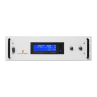
SM1500 GENERAL
rev. August 2018 DELTA ELEKTRONIKA B.V. Page 3 - 3
The Over Tem per a ture Sta tus or OT sta tus is "1" in case of an over tem per a ture,
the OT LED will be on and the out put shuts down. As a pre-warning the OT LED
starts to blink when the unit runs hot but the sit u a tion of over tem per a ture is not
reached yet. The sta tus will still be low when the LED is blink ing.
The Cur rent Con trol Sta tus or CC-status out put is "1" when the unit is in
CC-mode.
The Power Sink Over Load Sta tus or PSOL-status out put is "1" when the op tional
Power Sink is over loaded or over heated.
The AC-Fail Sta tus or ACF-sta tus out put is "1" when the in put volt age is be low
115 V (peak, not rms) for more than 10 ms. Note that if you want the ACF-sta tus to
switch be fore the DCF-sta tus, the hold-up time has to be > 10 ms. This can be
achieved by re duc ing the load, see para graph 25) of this chapter.
The DC-Fail Sta tus or DCF-status out put is "1" when the out put volt age is ei ther
5% be low or above the set point.
When the unit is in CC-mode, DCF will al ways be "1", see pre vi ous paragraph 7).
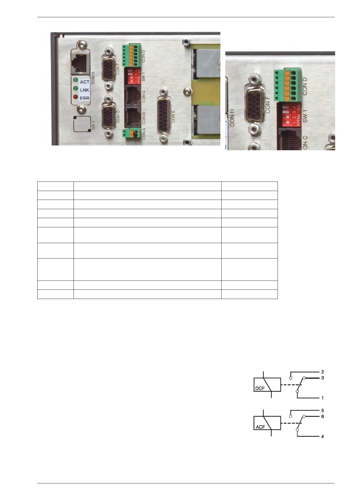
15) STATUS RE LAY OUT PUTS
The power sup ply has 2 sta tus re lay out puts, with each a change-over con tact.
They are con nected to con nec tor CON D. The pins 1, 2, 3 are con nected to the
DCF-re lay and pins 4, 5, 6 to the ACF-re lay (see fig. 3 - 10). Pin 1 is the lower
out put, clos est to SW1.
fig. 3 - 8 Location of out put ter mi nals and an a log pro gram ming con nec tor
CON A In ter lock Con nec tor para graph 18)
CON B Mas ter Connector for Mas ter / Slave op er a tion (out put) para graph 31)
CON C Slave Connector for Mas ter / Slave op er a tion (in put) para graph 31)
CON D Re lay Out puts, con tacts 1 - 6 ACF / DCF para graph 15)
CON E An a log Pro gramming Connector para graph 9)
CON F PSC-ETH, user inputs
PSC-232, from PC or pre vi ous PSC (op tional)
para graph 11)
CON G PSC-ETH, user outputs
PSC-232, to next PSC (op tional)
para graph 11)
CON H PSC-ETH (op tional) or
PSC-488 (op tional) or
ISO AMP CARD (op tional)
para graph 10), 11)
SW 1 Var i ous set tings para graph 16)
SW 2 Set tings for PSC-488 and PSC-232 (op tional) -
fig. 3 - 9 Connectors and switches on the rear panel
fig. 3 - 10
Sta tus re lay out puts on CON D.
This sit u a tion gives the re lay
po si tions dur ing fault con di tion.
Con nec tor D num ber ing
pin6
...
...
pin2
pin1
 Loading...