SM6000 DELTA ELEKTRONIKA BV
July 2003, rev. May 2008 OPERATING MAINTENANCE TROUBLE SHOOTING CALIBRATING Page 4 - 2
•
Connect the pro gramming voltage source(s) (0 - 5 V) to the
analog pro gramming con nector CON E on the rear panel (see
fig. 4 - 2 and fig. 4 - 3). Al ways use a shielded ca ble (max. 30
me ter) for pro gram ming.
• Turn the out put on again with the OUTPUT ON/OFF but ton.
• If only the voltage is pro grammed, the max imum current can
still be set with the CC knob on the front panel and vice versa.
If this is not de sirable the unit can be or dered with Option P001
or Op tion P220 in or der to have a fixed set ting for the CV and
the CC knob on the front panel, see also par. 34) in pre vious
chap ter "De scrip tions".
• To avoid hum or noise, the pro gramming ca ble may have to
be twisted in some cases.
• To pro gram the unit by current in stead of volt age, sim ply use a
parallel re sistor as a current to volt age con verter.
• Pressing the DISPLAY SETTINGS but ton will show the pro -
grammed values for CV and CC.
• CAU TION: The an alog in puts are not iso lated from the output.
The Ø of the prog. in put (pin 1) is in ternally con nected to the
S–, the S– is con nected to the neg ative output. To pro tect the
internal wir ing a 650 mA self-resetting fuse is con nected in se -
ries (F27_1 on P598). To avoid earth loops, use an isolated
programming source. If this is not pos sible, see nest para -
graph 4) for us ing the op tional ISO AMP CARD.
4)
AN A LOG PRO GRAMMING WITH ISO AMP CARD
• For pro gramming via the ISO AMP CARD, set DIP switch 1 on
SW1 in the po sition OFF.
• When the ISO AMP CARD is built in side the unit, CON E has
been re moved. Use CON H in stead. The pin ning of CON H is
equal to the pin ning of CON E .
• For fur ther op er at ing in struc tions, see pre vi ous para graph 3).
5)
IEEE488 / RS232 PRO GRAMMING
• Set DIP switch 1 on SW1 in po sition OFF for pro gramming
with the PSC-488 us ing CON H or programming with the
PSC-232 us ing CON F and G. With DIP switch 1 in this
po si tion, the sig nals Vprog (pin 11) and Iprog (pin 3) are
disabled on CON E. All the other sig nals can still be used.
• Set the unit in RE MOTE CV for volt age pro gramming and/or in
REMOTE CC for cur rent pro gramming us ing the SCPI com -
mands (see man ual PSC) or us ing the RE MOTE/LOCAL but -
ton on the unit. Push this but ton sev eral times un til the right
setting is activated. Set ting the unit in RE MOTE or LO CAL will
cause the output to shutdown to avoid accidental dam age to
the load. Turn it on again using the SCPI com mand or with the
OUTPUT ON/OFF button.
• Set DIP switch 1 on SW1 in po sition ON to enable CON E
again for an a log pro gram ming.
In this po sition voltage and cur rent pro gramming on CON F
and H is dis abled. The other func tions and signals can still be
programmed and read back.
6)
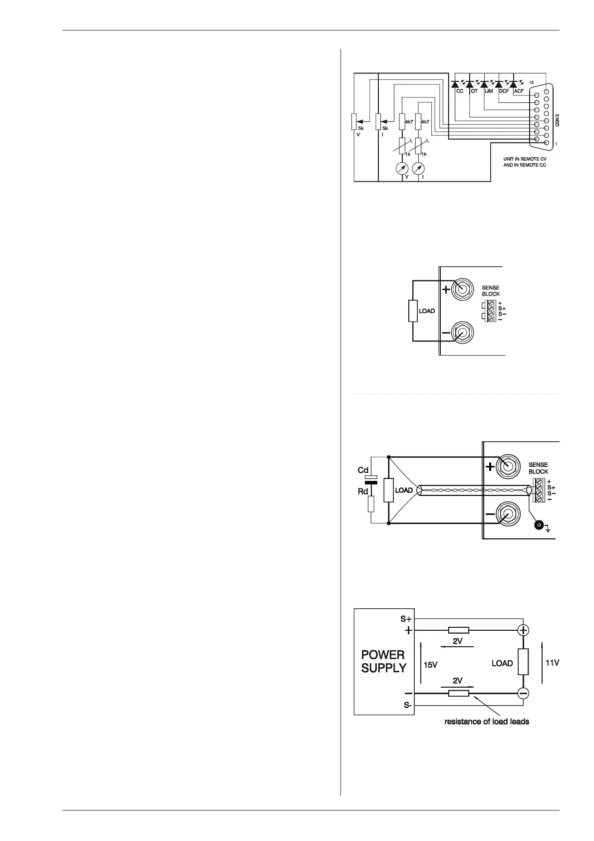
MON I TORING OUT PUTS
• The 5 V level is com patible with most in terfaces.
• The mon itoring out puts can drive a me ter di rectly
(see fig. 4 - 4).
7)
STATUS OUT PUTS
• The status outputs have a separate Ø con nection (pin 8) to
avoid un wanted offsets in the pro gramming. This pin is pro -
tected with a 650 mA self re setting fuse (F27_2 on P598).
8)
RE MOTE SENSING
• Remove the links on the SENSE BLOCK (on rear panel) and
connect sense leads (thin shielded mea suring wires) to S+
and S–. See fig 4 - 5 and fig. 4 - 6.
• With remote sensing the voltage on the load can be kept con -
stant. The voltage drop in the load leads will be com pensated.
This feature is not rec ommended for normal use, be cause it
can eas ily give prob lems.
fig. 4 - 4
Re mote con trol
fig. 4 - 5
Lo cal sens ing
fig. 4 - 6
Remote sensing with shielded wires
fig. 4 - 7
Remote sensing, voltage drop in load leads sub -
tracts from max. output

 Loading...


