SM6000 DELTA ELEKTRONIKA BV
July 2003, rev. May 2008 DESCRIPTIONS Page 3 - 5
22) RFI SUP PRES SION
Both the in put and out put have RFI fil ters, re sulting in very low
conducted RFI to the line and load. Due to the out put fil ter the
output voltage is very clean, hav ing al most no spikes.
23)
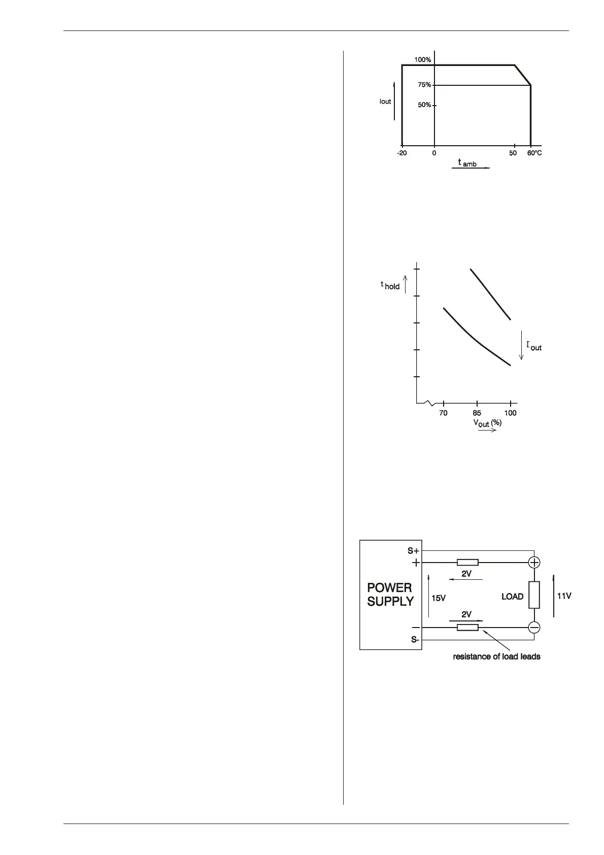
OP ER ATING TEMP
At full power the op erating tem perature range is –20 to +50 °C.
From 50 to 60 °C the output cur rent has to be de rated lin early to
75 % at 60 °C (see fig. 3 - 15). These tem peratures hold for nor -
mal use, i.e. the ven tilation open ings on the left and right side
must be free.
24)
THER MAL PRO TEC TION
A ther mal switch shuts down the out put in case of in sufficient
cool ing.The OT sta tus will be high. Af ter cool ing down the unit
will start work ing again.
The OT-LED on the front panel will be on and the OT-status sig -
nal will be "1" in case of a tripped ther mal pro tection.
As a pre-warning the OT-LED blinks (sta tus will still be low), this
will start be fore the power sup ply shuts down.
25)
HOLD - UP TIME
The hold - up time de pends on the load and the out put voltage.
A lighter load or a lower output voltage re sults in a lon ger hold -
up time (see fig. 3 - 16).
26)
TURN ON DE LAY
The out put voltage is avail able about 0.2 sec af ter mains switch
on.
27)
IN RUSH CUR RENT
The in rush cur rent is elec tron i cally lim ited.
Repeatedly switching on and off does not change the max imum
peak cur rent.
Switching on and off at a fast rate can overheat the in rush cur-
rent limiter. With the re sult that the unit does not start any more.
After cool ing down (mains switched off) it will be OK again.
28)
PHASE LOSS
Phase loss means that not all three phases are available.
The ACF-status will be high, the ACF LED will light and the
output of the unit will shutdown af ter a few seconds.
29)
RE MOTE SENSING
The voltage at the load can be kept con stant by re mote sensing.
This feature is not rec ommended for normal use but only when
the load voltage is not al lowed to vary a few millivolts. Al ways
use a shielded ca ble for sensing.
In or der to compensate for the voltage drop across the load
leads, the unit will have to sup ply a higher voltage (see fig. 3 -
17):
Uout = (volt age drop across each lead) + (voltage across the load).
The voltage limit reads the voltage di rectly at the output termi-
nals. The set ting for the limit must therefore be in creased by the
total voltage drop across the load leads.
The voltage dis play on the front panel and the volt age mon itor
output on CON E are con nected to the sense leads and there -
fore read the volt age across the load and not the voltage on the
out put ter mi nals.
The sense leads are pro tected against ac ci den tal in ter rup -
tion. The max imum voltage be tween the output terminals and
the sense in puts is limited at 2.5 V.
For sensing on a pul sat ing load see para graph 20) of this
chap ter.
fig. 3 - 15
Op er ating tem per a ture ranges
fig. 3 - 16
Hold-up time vs V
out
with I
out
as a pa ram e ter
fig. 3 - 17
Remote sensing, voltage drop in load leads sub -
tracts from max. output

 Loading...


