DELTA ELEKTRONIKA BV SM6000
Page 4 - 1 OPERATING MAINTENANCE TROUBLE SHOOTING CALIBRATING July 2003, rev. May 2008
OPERATING MANUAL
1) OPERATING THE UNIT FOR THE FIRST TIME
• Check there is no con densation on the unit. If there is, al low some
time to dry.
• Check there is a link be tween + and S+ and be tween – and S– on
the SENSE BLOCK (on rear panel).
• Check there is a link be tween the in puts of the In terlock (CON A,
rear panel).
• Set the CV and CC po tentiometers to min imum (fully anti clock-
wise). For units with Option P220, this is not needed. These units
are set to start at 0 V - 0 A when op erated for the first time.
• For ca ble di ameters and mounting torque (see ta ble 4 - 1).
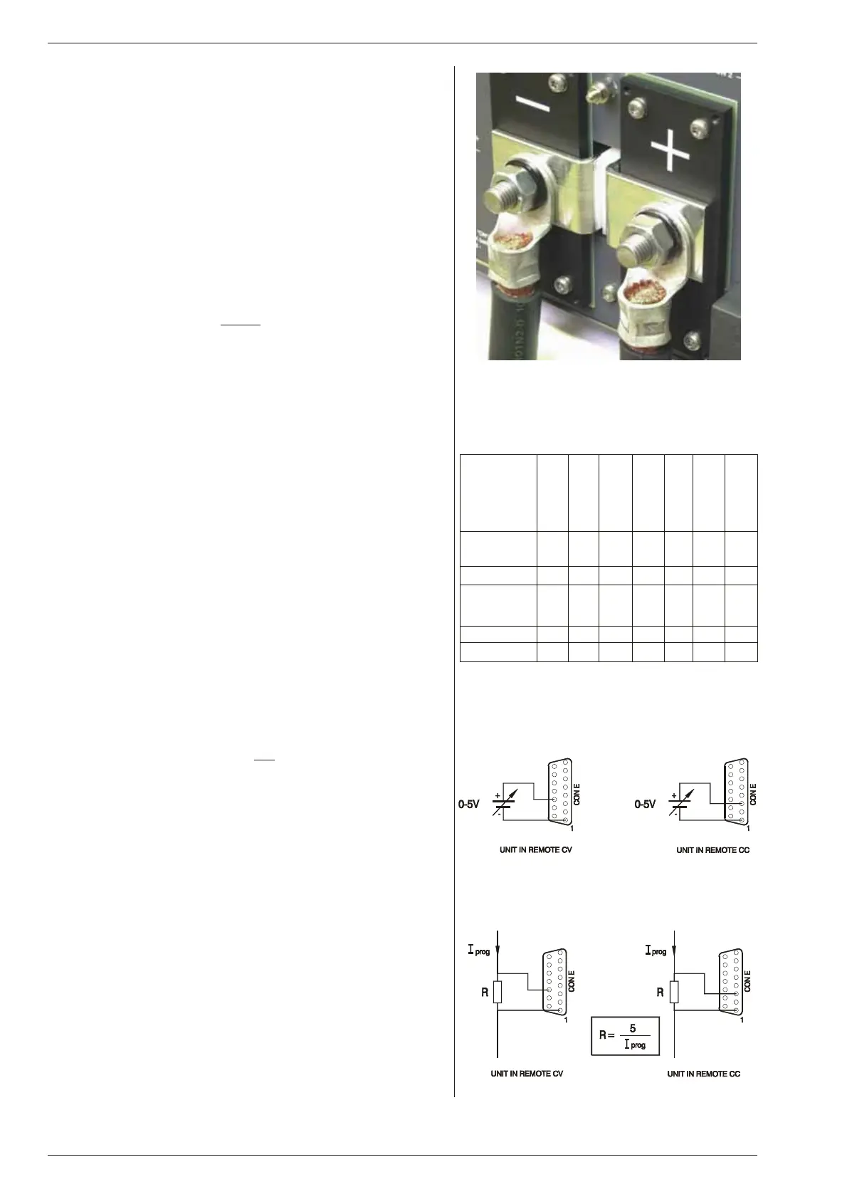
• With high out put current make sure to use low resistive con -
nections be tween the power sup ply and the load:
- Mount the ca ble lugs di rectly
on the tinned output strips
fol lowed by a washer, a split washer and a nut (see fig. 4 - 1).
Al ways in this or der!
- Never place wash ers be tween the lugs and the strips
be cause this can re sult in excessive heat!
- Only use nuts and wash ers sup plied with the unit.
• Switch on unit.
• Disable the Key lock function, see next para graph 2) .
• Check the unit is not in Re mote CV or Re mote CC (LED’s for this
function should be off). Press the RE MOTE/LOCAL but ton un til
both LED’s are off.
• Turn on the out put by pressing the OUTPUT ON/OFF but ton.
• Turn both the CV and CC po tentiometer a few turns clockwise.
A volt age should now be pres ent on the output.
• By pressing the DISPLAY CV/CC SETTING button the meters
will show the setting of the CV and CC po tentiometer.
• By pressing the DISPLAY LIMITS but ton the voltmeter will show
the setting of the CV-limit and the CC-limit potentiometer.
• Check that the cool ing of the unit is not ob structed.
2)
KEY LOCK
• If the func tion KEYLOCK is activated, it is no lon ger pos sible to
operate the REMOTE/LOCAL but ton and the OUTPUT ON/OFF
button. This func tion can be use ful to protect the out put from ac ci-
dental shutdown. The function KEYLOCK does not in fluence the
operating of the CV, CC, CV-limit and CC-limit po tentiometers.
• Units with dig ital encoders:
For units with Option P220 also the dig ital encoders for CV and
CC are dis abled with the Keylock function. This means settings
of the voltage and cur rent do not
change when the encoders are
operated. It is still pos sible to op erate the an alog CV-limit and
CC-limit po ten ti om eters.
• Ac ti vate Key lock:
Pressing the but tons DISPLAY SETTINGS and DIS PLAY
LIMITS at the same time for more than 3 seconds, ac tivates the
function KEYLOCK. The mo ment this func tion is activated, the
LED’s for RE MOTE CV / CC and for OUTPUT ON will blink a few
times.
• Dis able Key lock:
Pressing the same buttons again for 3 sec onds, dis ables the
Keylock function. The LED’s for RE MOTE CV / CC and for OUT-
PUT ON will blink again to in dicate the new set ting.
3)
AN A LOG PRO GRAMMING
• Set DIP switch 1 of SW1 in po sition ON to se lect CON E for pro-
gram ming.
• Dis able Key lock.
• Set the unit in RE MOTE CV for volt age pro gramming and/or in
REMOTE CC for cur rent pro gramming.
Use the RE MOTE/LOCAL but ton and push this but ton sev eral
times un til the right setting is activated.
Note that pushing the RE MOTE/LOCAL but ton will shutdown the
output to avoid ac cidental dam age to the load.
fig. 4 - 1
Low re sis tive ca ble con nec tion by mount ing the
cables di rectly on the tinned out put strips
fig. 4 - 2
Pro gram ming by volt age:
left voltage -, right current pro gramming
fig. 4 - 3
Pro gram ming by cur rent
left voltage -, right current pro gramming
Unit
SM 15-400
SM 30-200
SM 45-140
SM 60-100
SM 70-90
SM 120-50
SM 300-20
In put ca bles
[mm2]
2.5 2.5 2.5 2.5 2.5 2.5 2.5
Torque [Nm]
0.6 0.6 0.6 0.6 0.6 0.6 0.6
Out put ca bles
[mm2]
120 50 25 16 16 6 4
Bolts M12 M10 M10 M10 M10 M8 M8
Torque [Nm]
80 40 40 40 40 20 20
ta ble 4 - 1
Ca ble di am e ters and torque

 Loading...


