DELTA ELEKTRONIKA BV SM6000
Page 4 - 7 OPERATING MAINTENANCE TROUBLE SHOOTING CALIBRATING July 2003, rev. May 2008
6) MASTER / SLAVE PAR ALLEL PROB LEMS
• Check the voltage drop of the wir ing be tween the master and the
slaves is < 10 mV.
• Check the wiring has a low in ductance.
7)
OUTPUT VOLT AGE IS HIGHER THAN SET VALUE
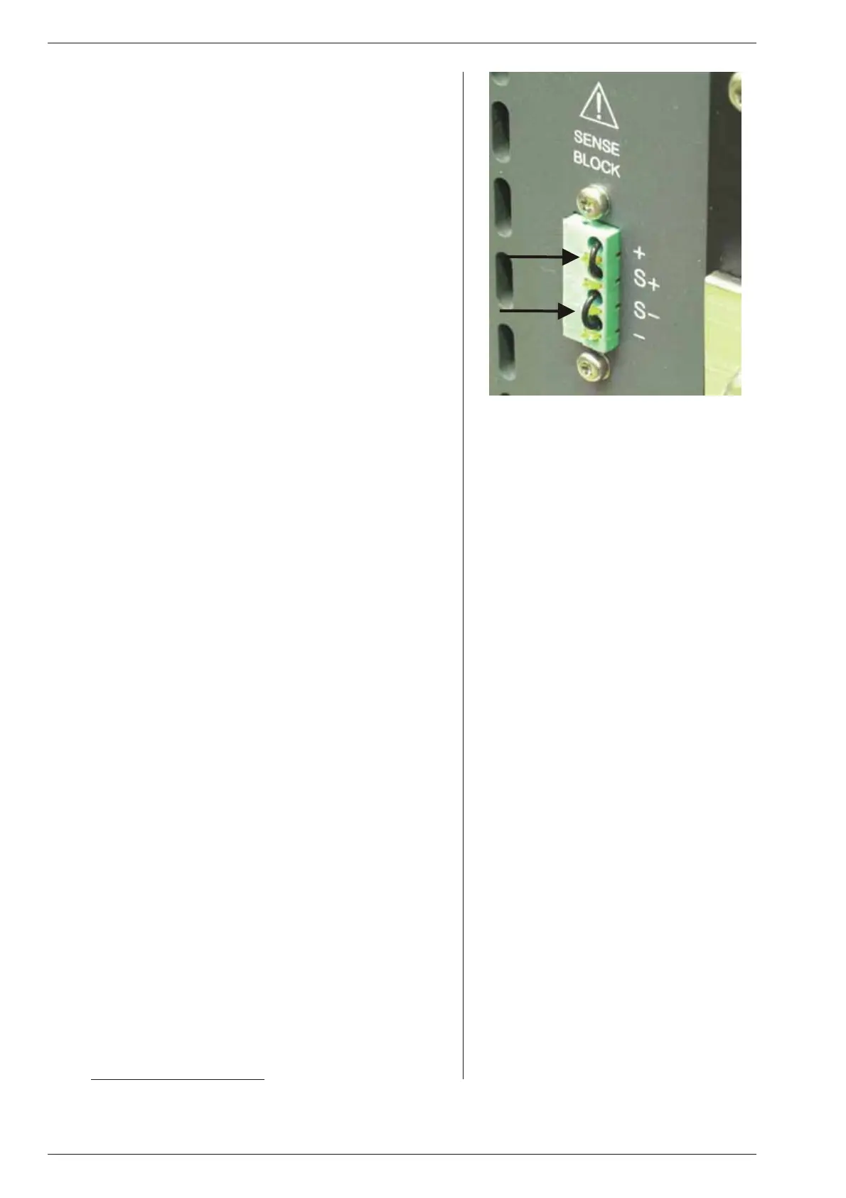
• Check con nections on SENSE BLOCK (on rear panel), For nor -
mal op eration there should be a link be tween + and S+ and be -
tween – and S– (see also fig. 4 - 16). When re mote sensing is
used, check the wires of the sens ing.
8)
OT LED on
• The temperature of the in ternal heat sink is too high,
the out put has been shutdown to avoid overheating.
• Check if the cool ing fans are running.
• Check if the air temperature of the air in lets (left) is be low 50 °C
and the air flow is not ob structed.
9)
OT LED blinks
• The temperature of the in ternal heat sink is get ting too high, a fur -
ther in crease will shutdown the power supply.
• Check if the cool ing fans are running prop erly.
• Check if the air temperature of the air in lets (left) is be low 50 °C
and the air flow is not ob structed.
10)
ACF LED on
• Phase Loss, check in put.
• The in put voltage is too low or was in termittent be cause of a bad
connection. Disconnect the mains, wait a few minutes and try
again.
As soon as the ACF LED Iights, the settings for Re mote CV,
Remote CC and Keylock will be saved. If the unit turns back on, it
will have the same set tings. For the set ting of Output On/Off af ter
turning the unit back on, the po sition of DIP switch 2 on SW1 is de -
ter min ing.
If the ACF situation lasts a few seconds, the out put will shutdown.
The ACF prob lem has to be solved first, be fore the out put can be
turned on again.
• Internal er ror, send unit for re pair. See previous para graph 1).
11)
DCF LED on
• The out put voltage is below the set voltage. This au tomatically
happens when the unit is in CC-mode (CC LED is on).
Also with an interrupted In terlock con nector, the DCF LED will be
on.
• Internal er ror, send unit for re pair. See previous para graph 1).
12)
PSOL LED on
• The Power Sink is in overload or the temperature of the Power
Sink is too high. See datasheet of the Power Sink op tion for fur ther
de tails.
13)
Blinking LEDs RE MOTE CV, RE MOTE CC and
OUT PUT ON
• This in dicates the Keylock function is activated, see pre vious
para graph 2) in "op er at ing man ual".
14)
NO LEDS on
• Check in put.
• Do not try to re pair, but send for repair. See previous para graph 1).
15)
OTHER
• If the prob lem per sists, please fill out the RMA-form on our website
www.DeltaPowerSupplies.com
. See also previous para graph 1).
fig. 4 - 16
For nor mal op eration links should be con nected
between S+ and + and be tween S– and –

 Loading...


